

CRC校验码的多种Verilog实现方式
电子说
描述
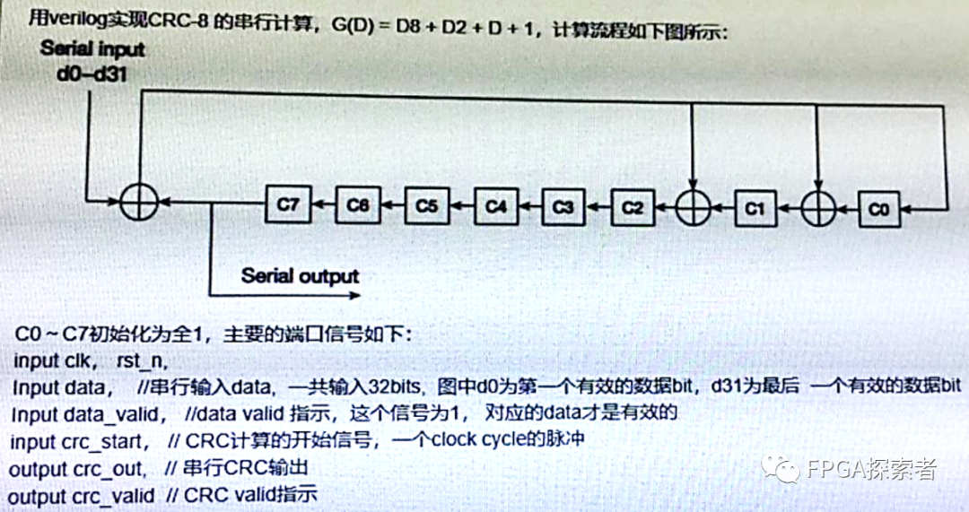
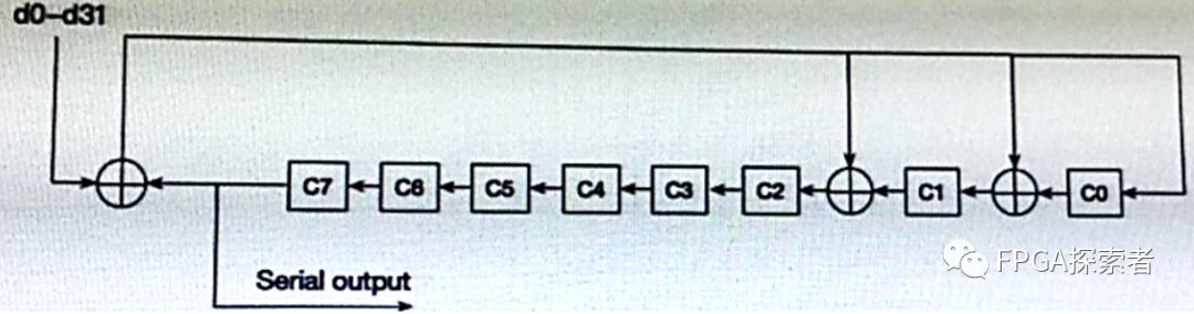
用Verilog实现CRC-8的串行计算,G(D)=D8+D2+D+1,计算流程如下图所示:
一、分析
CRC循环冗余校验码(Cyclic Redundancy Check),检错码。
(1)该题目所述为CRC-8,即输出8位CRC校验值,给定一段长为N-bit的有效输入序列,输出(N+8)-bit的数据,其中前N-bit数据为输入的原始数据,添加的8-bit数据为CRC校验数据;
(2)该CRC-8的生成多项式为G(D)=D8+D2+D+1,对CRC进行简化表示时可以忽略最高位的D8,结合图示中三个异或运算的位置更容易理解生成多项式,8位CRC有8个寄存器C0~C7,根据多项式,C0、C1和C2的输入是由异或运算而来;
二、Verilog编程
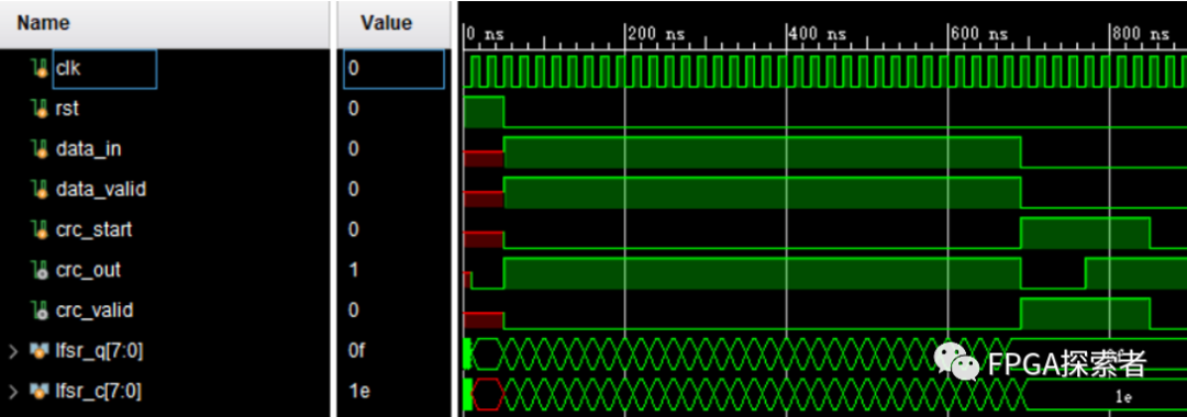
1. 并行计算,串行输出
对于输入位宽为1的输入,这种方法的计算非常简单,直接根据生成多项式运算。
(注意!如果输入位宽不为1,则需要根据多项式进行化简,可以使用http://outputlogic.com/?page_id=321生成运算逻辑和代码)
1.1 自己一步一步写
(1)先定义8个寄存器reg [7:0]
reg [7:0] crc_reg_q;// 寄存器 Q 输出端
reg [7:0] crc_reg_d;// 寄存器 D 输入端
(对crc_reg_d,使用always赋值就定义成reg,使用assign就定义成wire)
(2)异或计算
寄存器0的输入crc_reg_d[0],来自寄存器7的输出crc_reg_q[7]和数据输入data_in异或运算,即:
crc_reg_d [0] = crc_reg_q[7] ^ data_in;
同理可得:
always @ (*)
begin
       crc_reg_d[0] = crc_reg_q[7] ^ data_in;
crc_reg_d[1] = crc_reg_q[7] ^ data_in ^ crc_reg_q[0];
crc_reg_d[2] = crc_reg_q[7] ^ data_in ^ crc_reg_q[1];
crc_reg_d[3] = crc_reg_q[2];
crc_reg_d[4] = crc_reg_q[3];
crc_reg_d[5] = crc_reg_q[4];
crc_reg_d[6] = crc_reg_q[5];
crc_reg_d[7] = crc_reg_q[6];
end
上述使用组合逻辑实现异或运算和数据的传递,另外,对于每个寄存器的输入到输出(D端到Q端),使用时序逻辑,并且按照题目要求,设置初始值为全1,将数据有效标志作为控制逻辑:
always @ (posedge clk)
begin
    if( rst)
              crc_reg_q <= 8’hff;
       elsebegin
              if(data_valid )
                     crc_reg_q<= crc_reg_d;// 输入数据有效就更新值
else
                     crc_reg_q<= crc_reg_q;// 输入数据无效就等待
       end
end
(3)串行输出
上述已经实现了并行的 CRC,计算出的 CRC 结果就是直接的 8 位 CRC,按照题目要求,需要串行输出 CRC 结果。
思路:写一个计数器,当需要输出 CRC 时,串行计数输出,实现并串转换。这里,由于题目给了一个信号 crc_start,我把这个信号作为 CRC 的标志,当 data_valid 有效时表示输入的是数据,当 data_valid 无效且crc_start 有效表示数据输入完毕,该输出 CRC 了。
reg [2:0] count;
always @ (posedge clk)
begin
    if(rst)begin
       crc_out <= 0;
        count<= 0;
    end
    elsebegin
       if(data_valid) begin
           crc_out <= data_in;
           crc_valid <= 1'b0;
        end
        elseif(crc_start)begin
           count <= count + 1'b1;
           crc_out <= crc_reg_q [7-count];
           crc_valid <= 1'b1;
        end
        elsebegin
           crc_valid <= 1'b0;
        end
    end
end
1.2 CRC Generator自动生成
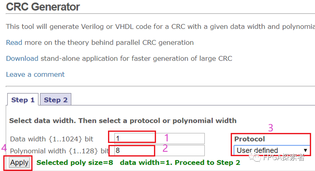
在Step1中,根据要求,1处表示输入数据位宽为1,2处CRC输出8位,3处选择自定义CRC的多项式,4处点击运用设定,然后进入Step2。
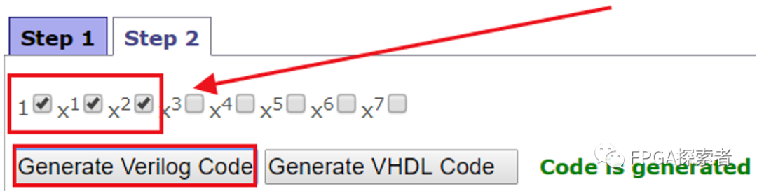
根据生成多项式,勾选1、X1、X2即可(对应1+D1+D2,最高位的D8不用管)。
//-----------------------------------------------------------------------------
// Copyright (C) 2009 OutputLogic.com
// This source file may be used and distributedwithout restriction
// provided that this copyright statement is notremoved from the file
// and that any derivative work contains theoriginal copyright notice
// and the associated disclaimer.
//
// THIS SOURCE FILE IS PROVIDED "ASIS" AND WITHOUT ANY EXPRESS
// OR IMPLIED WARRANTIES, INCLUDING, WITHOUTLIMITATION, THE IMPLIED
// WARRANTIES OF MERCHANTIBILITY AND FITNESS FORA PARTICULAR PURPOSE.
//-----------------------------------------------------------------------------
// CRC module for data[0:0] ,  crc[7:0]=1+x^1+x^2+x^8;
//-----------------------------------------------------------------------------
module crc(
  input [0:0] data_in,
  input crc_en,
  output [7:0] crc_out,
  input rst,
  input clk);


  reg [7:0] lfsr_q,lfsr_c;


  assign crc_out = lfsr_q;


  always @(*) begin
    lfsr_c[0] = lfsr_q[7] ^ data_in[0];
    lfsr_c[1] = lfsr_q[0] ^ lfsr_q[7]^ data_in[0];
    lfsr_c[2] = lfsr_q[1] ^ lfsr_q[7]^ data_in[0];
    lfsr_c[3] = lfsr_q[2];
    lfsr_c[4] = lfsr_q[3];
    lfsr_c[5] = lfsr_q[4];
    lfsr_c[6] = lfsr_q[5];
    lfsr_c[7] = lfsr_q[6];


  end // always


  always @(posedge clk, posedge rst) begin
    if(rst) begin
      lfsr_q <= {8{1'b1}};
    end
    else begin
      lfsr_q <= crc_en ? lfsr_c: lfsr_q;
    end
  end // always
endmodule // crc
将上述代码按照题目要求改变输入输出的名称,并进行串并转换(并->串)即可。
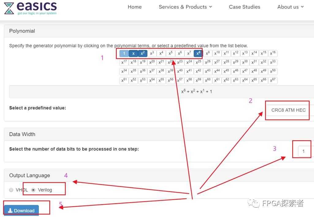
1.3 easics自动生成
https://www.easics.com/crctool
(1)1处选择CRC的生成多项式,这里与1.2的不同在于,要把最高位的D8选上,easics能识别的CRC协议更多;
(2)2处自动识别出这个CRC多项式其实是CRC8 ATM HEC协议使用的 CRC;
(3)3处设置输入数据位宽为1;
(4)选择生成Verilog代码;
(5)下载代码。
仔细阅读代码注释,注意!
convention: the first serial bit is D[0]
数据的最低位先输出,此代码将会把低位作为异或移出位,而上面已经提到的两种方法均是将最高位作为移出位去异或,所以,代码中需要稍作修改,将d[0]改成d[7],d[1]改成d[6],…,以此类推,c[0]- c[7]不要变。
有兴趣的可以去看看【大小端问题】,在不同处理器、不同协议中非常常见。
///////////////////////////////////////////////////////////////////////////////
// Copyright (C) 1999-2008 Easics NV.
// This source file may be used and distributedwithout restriction
// provided that this copyright statement is notremoved from the file
// and that any derivative work contains theoriginal copyright notice
// and the associated disclaimer.
//
// THIS SOURCE FILE IS PROVIDED "AS IS"AND WITHOUT ANY EXPRESS
// OR IMPLIED WARRANTIES, INCLUDING, WITHOUTLIMITATION, THE IMPLIED
// WARRANTIES OF MERCHANTIBILITY AND FITNESS FOR APARTICULAR PURPOSE.
//
// Purpose : synthesizable CRC function
//   *polynomial: x^8 + x^2 + x^1 + 1
//   * datawidth: 1
//
// Info : tools@easics.be
//       http://www.easics.com
///////////////////////////////////////////////////////////////////////////////
module CRC8_D1;


  //polynomial: x^8 + x^2 + x^1 + 1
  // datawidth: 1
  //convention: the first serial bit is D[0]
  function[7:0] nextCRC8_D1;


    inputData;
    input[7:0] crc;
    reg [0:0]d;
    reg [7:0]c;
    reg [7:0]newcrc;
  begin
    d[0] =Data;
    c = crc;


    newcrc[0]= d[0] ^ c[7];
    newcrc[1]= d[0] ^ c[0] ^ c[7];
    newcrc[2]= d[0] ^ c[1] ^ c[7];
    newcrc[3]= c[2];
    newcrc[4]= c[3];
    newcrc[5]= c[4];
    newcrc[6]= c[5];
    newcrc[7]= c[6];
   nextCRC8_D1 = newcrc;
  end
  endfunction
endmodule
2. 串行计算,串行输出(函数function用法)
CRC计算的重要思想是不断的消除最高位。
(1) 新建函数function
Verilog函数名为next_crc,输入信号为 data_in 和 current_crc,输出信号为8位的新 crc。
函数功能为:根据输入信号data_in,跳转CRC的状态;
函数的设计逻辑为:
(a)将CRC寄存器的数据左移1位,低位补零,得到
{current_crc[6:0],1'b0} (其中{ }为位拼接符);
(b)新输入的数据data_in和移出的CRC最高位做异或得到
current_crc[7]^data_in;
(c)使用位拼接符对异或结果进行位扩展,CRC-8进行8位的扩展,得到
{8{current_crc[7]^data_in}};
(d)扩展后的数据和生成多项式进行与运算,得到
{8{current_crc[7]^data_in}} & (8'h07);
(e)将(a)的数据和(d)的数据进行异或运算,得到CRC结果;
next_crc = {current_crc[6:0],1'b0} ^({8{current_crc[7]^data_in}} & (8'h07));
上述,(a)是对CRC低位的处理,(b)-(d)是对CRC最高位的处理。
8’h07从何而来?
因为生成多项式G(D) = D8+D2+D1+D0,前面提到了最高位的D8不用管,那么使用8位去表示为 0000_0111,即低3位为1,其余为0,即8’h07。
function [7:0] next_crc;
    inputdata_in;
    input[7:0] current_crc;


    begin
       next_crc = {current_crc[6:0],1'b0} ^ ({8{current_crc[7]^data_in}} &(8'h07));
    end


endfunction
(2) 调用function函数
初始化时给寄存器赋值全为1,当数据有效时,进行CRC计算。
reg [7:0] crc_reg;
always @ (posedge clk)
begin
    if(rst)begin
       crc_reg <= 8'hff;
    end
    elsebegin
       if(data_valid) begin
           crc_reg <= next_crc(data_in, crc_reg);
        end
    end
end
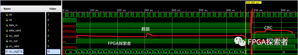
(3) 串行输出(串并转换)
按照上面的老方法,串并转换(并->串)。
输入32个1,先输出输入的32个1,紧跟着输出32个1的CRC校验值8’b00001111。
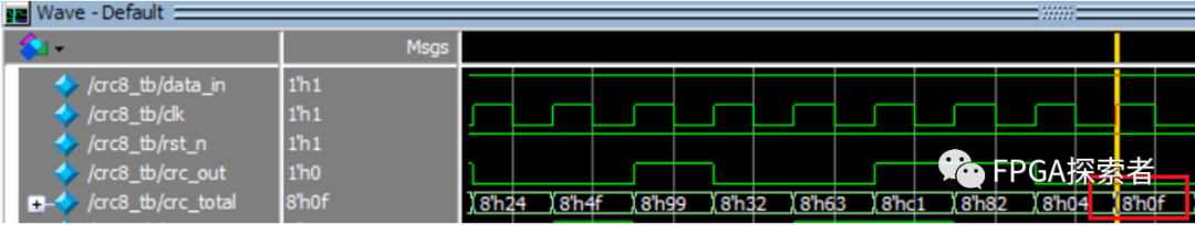
三、原理图设计
使用Quartus原理图设计,调用DFF触发器和XOR异或门搭建题目所示的CRC逻辑。
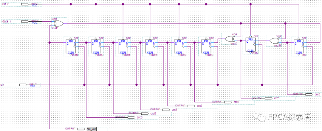
这里没有做data_valid的控制,输入数据是连续的32个1,输入完成后的CRC值是8’h0f,串行输出8位二进制数据 8’b00001111。
四、扩展
1. 并行计算并行输出
(1)对于单bit输入的序列,只要将并行计算串行输出的串并转换去掉,直接输出8-bit的CRC校验值即可;
(2)对于多bit同时输入的序列,通过介绍的两个在线平台去生成运算逻辑(笔试肯定不会丧心病狂到考多bit并行);
2. 查表法
实际工程中,为了减少运算量,还经常使用一种查表法,将CRC的校验表直接存储在ROM中,进行索引查找,常见的CRC表可以自行去查找,这里只是抛砖引玉。
-
如何在IAR Embedded Workbench中配置生成对应代码区域的CRC校验码2023-10-27 3447
-
CRC校验码的多种Verilog实现方式2023-06-21 4601
-
工控常用LRC XOR累加和CRC校验工具校验码自动生成软件多计算方式2022-11-25 6015
-
CRC16的计算校验码的方式有哪几种?2021-11-03 3102
-
CRC校验码并行计算的FPGA实现2021-03-28 1942
-
CRC校验码的C语言程序免费下载2020-04-22 1227
-
CRC计算工具CRC校验码计算器应用程序免费下载2019-07-01 5161
-
荐读:基于FPGA 的CRC校验码生成器2018-06-13 7320
-
crc循环冗余校验码算法2017-12-04 24268
-
CRC-16校验码生成2016-05-06 1008
-
CRC校验码算法的研究与实现2012-05-28 1126
-
奇偶校验码,奇偶校验码原理是什么?2010-03-17 63741
-
循环冗余校验码---CRC码2009-10-13 7558
-
电话网远程通信中CRC校验码的设计及实现2009-08-12 991
全部0条评论

快来发表一下你的评论吧 !
