
资料下载


大电流高边开关屏蔽BTS7002 1EPP开源
分享资料个
描述
盾牌到底是怎么回事?
这个 Arduino 扩展板带有 4 个高侧开关BTS7002-1EPP (每个输出的标称电流为 21A)。为了演示继电器和保险丝的更换,该屏蔽可用于控制和保护 12V 电源的输出、打开/关闭负载(例如灯泡、加热电阻器、电机驱动器)、测量负载电流和检测空载条件。PROFET™ +2 12V 系列针对大电流汽车应用(例如 ECU 电源、辅助电源插座、加热器)。
解剖盾牌
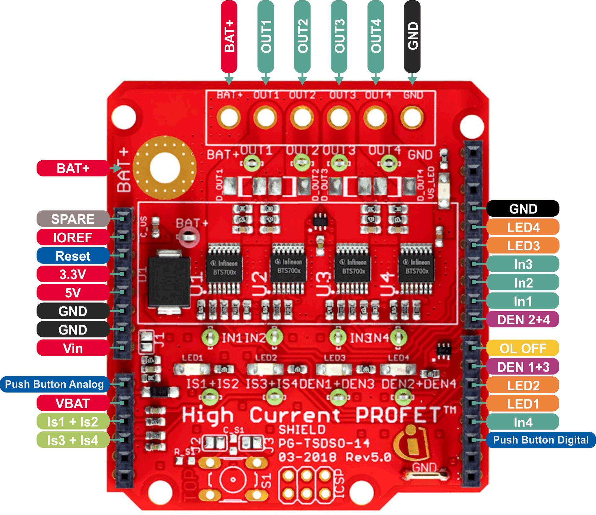
引脚定义和功能
Push button digital: Push button digital (optional).IN4: Input PROFET™+2 device U4.LED1: Indicator LED 1.LED2: Indicator LED 2.DEN 1+3: Diagnosis enable PROFET™+2 device U1+U3.OLOFF: Option for Open Load in OFF detection.DEN 2+4: Diagnosis enable PROFET™+2 device U2+U4.IN1: Input PROFET™+2 device U1.IN2: Input PROFET™+2 device U2.IN3: Input PROFET™+2 device U3.LED3: Indicator LED 3.LED4: Indicator LED 4.VIN: Supply voltage.Push button analog: Push button analog (optional).VBAT: Measuring of VBAT via voltage divider.IS 1+2: Current sense of PROFET™+2 device U1+U2.IS 3+4: Current sense of PROFET™+2 device U3+U4.
软件端
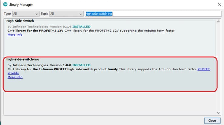
将插入屏蔽板的 Arduino 连接到您的计算机后,启动 Arduino IDE 并安装高端开关 ino 库。为此,请单击 Sketch,然后将鼠标悬停在 Include Library 上,然后单击 Manage Libraries... 在搜索栏中:键入 high side switch ino,然后您将找到安装库的选项。
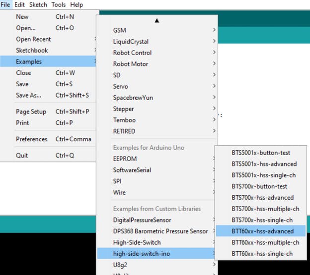
现在该库已正确安装,您可以选择探索各种预先编写的代码示例。为此:只需单击文件,然后将鼠标悬停在示例和高端开关上,然后选择您想要的任何示例代码片段。
该库实质上为您省去了手动寻址代码中的每个引脚和控制屏蔽的麻烦,包括用于通道控制的模拟输出信号、用于启用诊断功能的数字输出以及用于使用英飞凌电流感应诊断功能的模拟输入。
设置代码
我们首先包含我们的库,然后使用 hss 命名空间
#include
因此,我们用我们想要的任何名称来实例化一个屏蔽对象(在我们当前拥有的代码片段的情况下:它是 HSS)。此外,我们还实例化了一个错误变量,其中设置了一个名为 OK 的定义的值(您将在下面知道原因)。
Bts700xShieldIno HSS = Bts700xShieldIno(&BTS7002);
Error_t err = OK;
进入我们的设置函数:我们所要做的就是初始化我们刚刚使用 init() 函数实例化的 HSS 对象。此函数返回一个错误代码,我们将与我们最初分配给错误变量的值(OK 定义)进行比较。为确保一切正常,您可以检查控制器告诉我们初始化是否成功的串行监视器。如果您遵循所有这些,您的代码现在应该如下所示:
#include
可能返回的错误代码有:
OK:No error INTF_ERROR: Interface error CONF_ERROR: Configuration error READ_ERROR: Read error WRITE_ERROR: Write error NULLPTR_ERROR: Null pointer error INVALID_CH_ERROR: Invalid channel error UNSUPPORTED_OP_ERROR: Invalid channel error INIT_ERROR: Not initialized
活动软件组件
现在设置已完全完成,我们可以选择实际控制开关通道并检查通道的诊断。对于我们的高端开关通道控制,我们有两个主要功能,即switchesHxOn(bool out1= false, bool out2= false, bool out3= false, bool out4= false)和switchesHxOff(bool out1= false, bool out2= false, bool out3= false, bool out4= false)。
这两个函数采用 4 个值(0s 或 1s / true 或 false)表示它们的目标操作通道。switchHxOff()您还可以使用或函数一次打开/关闭单个通道switchHxOn(),其中两者都采用目标输出通道号。
以下代码片段将所有屏蔽通道打开三秒钟,然后将它们再次关闭连续三秒钟。
void loop(){
HSS.switchesHxOn(1,1,1,1);
delay(3000);
HSS.switchesHxOff(1,1,1,1);
delay(3000);
}
诊断:
我们用于诊断的库的 MVP 函数是 readDiagx(uint8_t x) 函数。此函数返回 DiagStatus_t 类型值。它接受一个从 1 到 4 的数字,代表输出通道号。
返回的诊断状态可能是:
DIAG_READ_ERROR: Read Error NOT_ENABLED: Diagnosis not enabled NORMAL Switch works correctly FAULT: Switch is in fault condition (Is_fault at IS pin), which can mean “Short to GND”, “Overtemperature” or “Overload” FAULT_OL_IC: Switch is either in Open Load (whit enable channel) or inverse current is flowing SHORT_TO_GND_OR_OT: Short to the ground or Overtemperature detected SHORT_TO_VSS: Short to the supply voltage OPEN_LOAD: Open load detected
另一个诊断功能是英飞凌的电流感应功能,它使我们能够找出流过负载的电流值。负责读取电流的功能是readIsx()。该readIsx()函数以浮点数的形式返回电流值,单位为安培。
为了增加交易,该readVss()函数读取 vBAT 引脚上的电压(检查上图)并以浮点形式以伏特为单位返回。
以下代码片段取自库中的 BTS700x-hss-advanced 代码示例片段。自定义函数 getSwitchParams() 具有三个内置自定义函数,每个函数都使用本节中提到的函数提供诊断信息:
void getSwitchParams(int switch_no)
{
    Serial.println("Reading the current, battery voltage and diagnosis status of switch ...");
    /** Read current value */
    readCurrent(switch_no);
    /** Get diagnosis result */
    readDiagnosis(switch_no);
    /** Read battery voltage */
    readBatteryVoltage();
}


/**
 * @brief       Read current flowing through the switch
 * @param   switch_no  Switch number
 */
void readCurrent(int switch_no)
{
    float readAmps = 0.0;
    readAmps = HSS.readIsx(switch_no);
    Serial.print("Current flowing through the switch: ");
    Serial.print(readAmps);
    Serial.println(" A");
    return;
}

/**
 * @brief       Read diagnosis status of the switch
 * @param   switch_no  Switch number
 */
void readDiagnosis(int switch_no)
{
    DiagStatus_t switchStatus;

    for(int i = 0; i<10; i++){
        switchStatus = HSS.readDiagx(switch_no);            // Read the diagnosis function more than once to make sure the IS value is correct (internal exponential filter)
    }

    if(switchStatus == OPEN_LOAD)
    {
        Serial.println("Openload detected!");
    }
    if(switchStatus == FAULT)
    {
        Serial.println("Short circuit to ground detected, Overtemperature or Overload detected!");
    }
    if(switchStatus == FAULT_OL_IC)
    {
        Serial.println("Open load with active switch or inverse current detected!");
    }
    if(switchStatus == SHORT_TO_VSS)
    {
        Serial.println("Short circuit to Vss detected!");
    }
    if(switchStatus == NORMAL)
    {
        Serial.println("Normal operation!");
    }
    return;
}

/**
 * @brief       Reads the current battery voltage
 */
void readBatteryVoltage()
{
    float batteryVoltage = 0.0;
    for(int i = 0; i<10; i++){
        batteryVoltage = HSS.readVss();                 // Measure more than once to make use of the internal exponential filter
    }
    Serial.print("Current battery voltage : ");
    Serial.print(batteryVoltage);
    Serial.println(" V");
    return;
}
使用盾牌的按钮功能
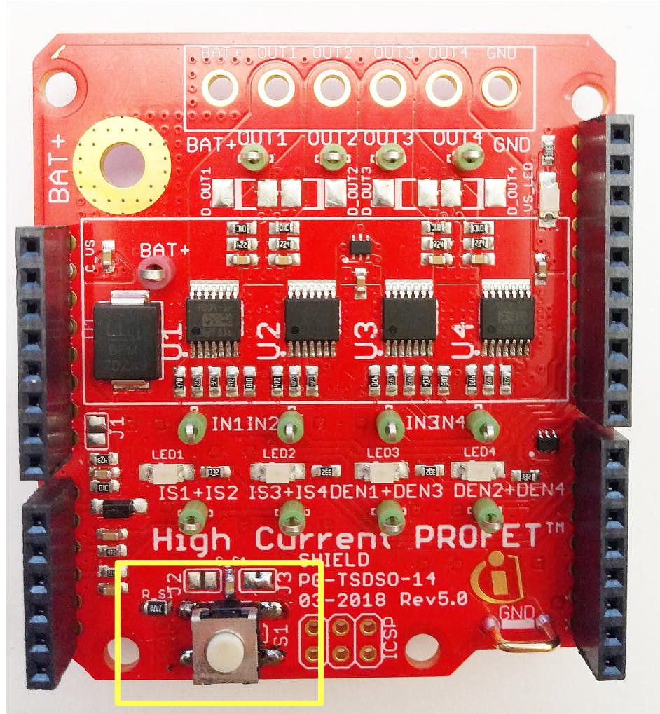
还提供在占位符 S1 处焊接 SMD 按钮的选项。此外,还需要一个电阻器 (RS1= 82 kOhm) 和一个电容器 (CS1 = 100 nF) 来对开关进行去抖动处理。此外,根据跳线 J2/J3 的设置,按钮可用于数字输入 D2 (P1.4) 或模拟输入 A0 (P2.6)。
哪里使用数字输入焊接跳线J3,而使用模拟输入焊接跳线J2
您实际上可以同时焊接跳线 J2 和 J3,这将允许您同时使用analogReadButton()和digitalReadButton()功能
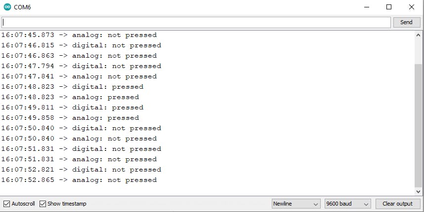
下面的代码片段演示了analogReadButton()和digitalReadbutton()函数的使用,如果按钮被按下,Arduino板串行打印“按下”,如果不是,则打印“未按下”:
void loop(){
if (HSS.digitalReadButton()){
    Serial.println("digital: pressed");
    }
 else {
       Serial.println("digital: not pressed");
       }
if (HSS.analogReadButton()){
    Serial.println("analog: pressed");
    }
 else {
       Serial.println("analog: not pressed");
       }
    delay(1000);
}
LED控制
屏蔽层的 LED 在操作各自的输出通道号时亮起(当您使用 HxSwitchesOn/HxSwitchOn 功能时),但是,如果只是通过向其引脚发送 PWM 信号来操作开关,它们不会亮起。要手动控制 LED:只需将数字高逻辑信号发送到四个 LED 引脚中的任何一个。
以下代码片段通过手动操作输出 3 的开关并同时打开 LED 1、2 和 4 来手动演示这一点。
//-------------PIN DEFINITIONS------------------------------
const int IN4 = 3;
const int LED1 = 4;
const int LED2 = 5;
const int DEN1_DEN3 = 6;
const int OLOFF = 7;
const int DEN2_DEN4 = 8;
const int IN1 = 9;
const int IN2 = 10;
const int IN3 = 11;
const int LED3 = 12;
const int LED4 = 13;
const int Button = A0;
const int IS_U1U2 = A2;
const int IS_U3U4 = A3;
//-------------END OF PIN DEFINITIONS------------------------
void setup() {
//------------- PIN MODE SETUP-------------------------------
pinMode(IN1,OUTPUT);
pinMode(IN2,OUTPUT);
pinMode(IN3,OUTPUT);
pinMode(IN4,OUTPUT);
pinMode(Button,INPUT);
pinMode(IS_U1U2,INPUT);
pinMode(IS_U3U4,INPUT);
pinMode(DEN1_DEN3,OUTPUT);
pinMode(DEN2_DEN4,OUTPUT);
pinMode(OLOFF,OUTPUT);
pinMode(LED1,OUTPUT);
pinMode(LED2,OUTPUT);
pinMode(LED3,OUTPUT);
pinMode(LED4,OUTPUT);
//-----------------END OF PIN MODE SETUP--------------------
}
void loop(){
analogWrite(IN3,255);
digitalWrite(LED1,HIGH);
digitalWrite(LED2,HIGH);
digitalWrite(LED4,HIGH);
}

声明:本文内容及配图由入驻作者撰写或者入驻合作网站授权转载。文章观点仅代表作者本人,不代表电子发烧友网立场。文章及其配图仅供工程师学习之用,如有内容侵权或者其他违规问题,请联系本站处理。 举报投诉
- 相关下载
- 相关文章


