
资料下载


×
将Arduino Uno与RGB LED连接
消耗积分:0 |
格式:zip |
大小:0.42 MB |
2022-11-14
王涛
分享资料个
描述
首先我们需要知道RGB LED是什么意思?
RGB LED 是蓝色 LED、绿色 LED 和红色 LED 的组合。它也被称为三色或多色LED。显然,有了这个 LED,您将能够产生红色、绿色和蓝色,您还可以通过配置每个 LED 的强度来产生不同的颜色。第一张图是一个简单的 RGB LED,第二张是 RGB LED 模块:
RGB LED 有四个引脚,即绿色引脚、蓝色引脚、红色引脚和阴极 (-)。阴极被认为是负引脚,它连接到系统的地。其他三个引脚控制它们各自的颜色。
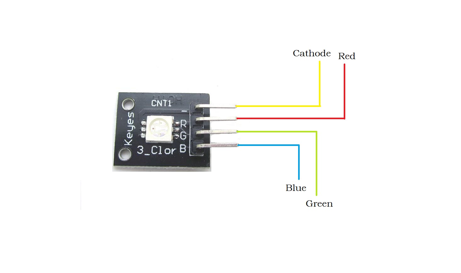
RGB灯管脚位图
现在我们可以开始连接了:
D13 到 Arduino 的绿色引脚
Arduino的D3引脚的蓝色引脚
Arduino的D5引脚的红色引脚
阴极 ( - ) 到 Arduino 的 Gnd
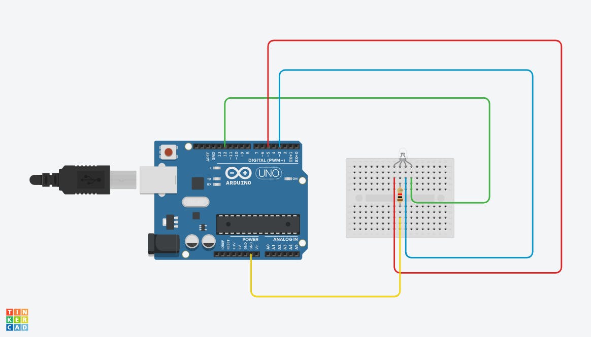
RGB灯电路图
电路图、图像和参考资料已上传到硬件部分。这是代码:
// Interfacing RGB led with Arduino Uno
int redPin = 5;// Red pin to digital pin 5 of arduino
int greenPin = 12;// Green pin to digital pin 12 of arduino
int bluePin = 3;// Blue pin to digital pin 3 of arduino
//uncomment this line if using a Common Anode LED
//#define COMMON_ANODE
void setup()
{
 pinMode(redPin, OUTPUT);
 pinMode(greenPin, OUTPUT);
 pinMode(bluePin, OUTPUT);
}
void loop()
{
 setColor(255, 0, 0);  // red
 delay(1000);
 setColor(0, 255, 0);  // green
 delay(1000);
 setColor(0, 0, 255);  // blue
 delay(1000);
 setColor(255, 255, 0);  // yellow
 delay(1000);
 setColor(80, 0, 80);  // purple
 delay(1000);
 setColor(0, 255, 255);  // aqua
 delay(1000);
}
void setColor(int red, int green, int blue)
{
 #ifdef COMMON_ANODE
   red = 255 - red;
   green = 255 - green;
   blue = 255 - blue;
 #endif
 analogWrite(redPin, red);
 analogWrite(greenPin, green);
 analogWrite(bluePin, blue);
}
要使用 RGB LED 创建更多颜色,我们需要设置每个内部 LED 的强度并组合三种颜色输出。我们将使用 PWM 分别调整红色、绿色和蓝色 LED 的强度,这里的技巧是我们的眼睛会看到颜色的组合,而不是单个颜色,因为 LED 彼此非常接近里面。这是RGB LED的颜色图表:
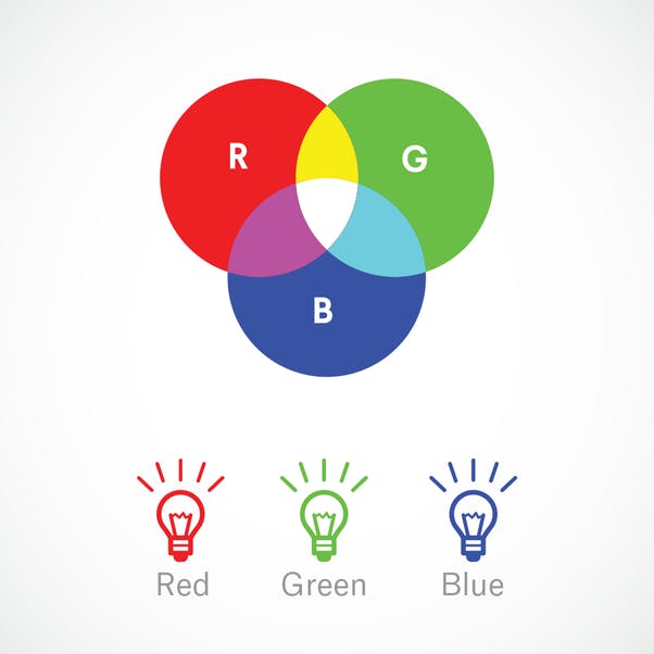
RGB LED 色卡

声明:本文内容及配图由入驻作者撰写或者入驻合作网站授权转载。文章观点仅代表作者本人,不代表电子发烧友网立场。文章及其配图仅供工程师学习之用,如有内容侵权或者其他违规问题,请联系本站处理。 举报投诉
评论(0)
发评论
- 相关下载
- 相关文章


