
资料下载


Neko Punk合成器V2开源分享
姬房有
分享资料个
描述
大家好,欢迎回来,这是我的 Neko Punk Synth Version 2,它是以猫为主题的合成器,由 Arduino Nano 和 Mozzi 库提供支持。
通过改变 5 个滑动罐的位置,Mozzi 可以产生更加复杂和有趣的咆哮、扫动和合唱声音。这些声音可以通过熟悉的合成单元(如振荡器、延迟和滤波器)快速轻松地构建。
我几周前制作的 Previous 版本是基于最初的 Atari Punk Console,最初是由Forrest Mims在1980 年制作的。它使用触发单稳态设置的非稳态多谐振荡器设置。通过组合这两个设置,我们得到一个步进音发生器或一个 atari 朋克合成器。
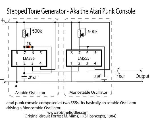
这很容易做,但我对它的结果不满意。
一年前,我用 Mozzi Library 制作了一个类似的合成器,效果非常好,所以我想为什么不在 Neko Punk Synth 的 V2 中使用 Mozzi,为了让事情变得超级酷,我使用了滑动罐,让这个合成器具有了赛博朋克的感觉——看起来。
所需材料
这些是这个建筑中使用的东西-
阿杜诺纳米
PAM8403 音频放大器
由PCBWAY提供的定制PCB
锂离子 5V 升压模块
3.7V 锂离子电池
3D 打印外壳
4欧喇叭
滑块盆
电路设计
V2 PCB 可能是我做过的最简单的电路板。
它使用 Arduino Nano 作为基础微控制器,五个滑块盆与 Arduino nano 连接。
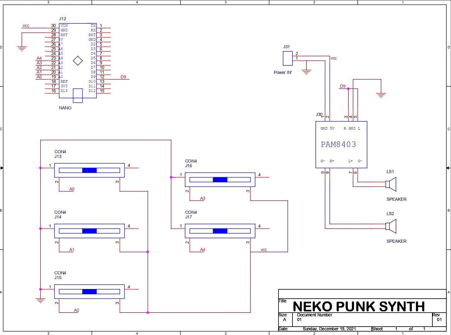
D9 进入 PAM8403 音频放大器模块的输入端,PAM8403 的输出端与两个 CON2 引脚相连,因此我们可以用它添加扬声器。
整个设置需要 5V 才能工作。
要为这个设置供电,我必须使用你可以在网上找到的这个锂离子电池升压模块,这些模块非常便宜而且工作得很好。
1 / 2
它将 3.7V 的锂离子电池升压至恒定的 5V 1A 或 2A,以便我们的 MCU 设置正常工作。
我在我的 OrCad PCB 套件中准备了 PCB,并添加了一些图形以增加电路板的美感。
从 PCBWAY 获取电路板
我在这个项目中使用了 PCBWAY PCB 服务。我在PCBWAY的报价页面上传了这个项目的Gerber文件。
对于这个 Synth 板,我选择了白色阻焊层颜色,因为我在板的顶部添加了很多圆形图形和自定义艺术。
黑色丝印搭配白色阻焊颜色看起来很棒。
我在一周内收到了 PCB,PCB 质量非常好,这个 PCB 很大,我喜欢这些 PCB 的质量没有因为尺寸而受到影响。
印刷电路板组装
现在这块板没有任何 SMD Componenets 所以我们只需要手动将所有东西放在这块板上并用烙铁焊接它们。
我首先收集所有材料并开始使用滑动电位器进行组装。
然后我将所有的 Pot 从顶部放在它们的位置,并从 PCB 的底部焊接它们的焊盘。
在此之后,我在它们的位置添加了 Arduino Nano 和 PAM8403 模块,组装就差不多完成了。
上传代码
这是基于 Mozzi 库的项目的主要草图。
/*
  Example using 2 light dependent resistors (LDRs) to change
  FM synthesis parameters, and a knob for fundamental frequency,
  using Mozzi sonification library.

  Demonstrates analog input, audio and control oscillators, phase modulation
  and smoothing a control signal at audio rate to avoid clicks.
  Also demonstrates AutoMap, which maps unpredictable inputs to a set range.

  This example goes with a tutorial on the Mozzi site:
  http://sensorium.github.io/Mozzi/learn/Mozzi_Introductory_Tutorial.pdf

  The circuit:
     Audio output on digital pin 9 (on a Uno or similar), or
     check the README or http://sensorium.github.com/Mozzi/

     Potentiometer connected to analog pin 0.
       Center pin of the potentiometer goes to the analog pin.
       Side pins of the potentiometer go to +5V and ground

     Light dependent resistor (LDR) and 5.1k resistor on analog pin 1:
       LDR from analog pin to +5V
       5.1k resistor from analog pin to ground

     Light dependent resistor (LDR) and 5.1k resistor on analog pin 2:
       LDR from analog pin to +5V
       5.1k resistor from analog pin to ground

  Mozzi help/discussion/announcements:
  https://groups.google.com/forum/#!forum/mozzi-users

  Tim Barrass 2013.
  This example code is in the public domain.
*/

#include
#include  // oscillator
#include  // table for Oscils to play
#include
#include  // maps unpredictable inputs to a range

// int freqVal;

// desired carrier frequency max and min, for AutoMap
const int MIN_CARRIER_FREQ = 22;
const int MAX_CARRIER_FREQ = 440;

const int MIN = 1;
const int MAX = 10;

const int MIN_2 = 1;
const int MAX_2 = 15;

// desired intensity max and min, for AutoMap, note they're inverted for reverse dynamics
const int MIN_INTENSITY = 700;
const int MAX_INTENSITY = 10;

// desired mod speed max and min, for AutoMap, note they're inverted for reverse dynamics
const int MIN_MOD_SPEED = 10000;
const int MAX_MOD_SPEED = 1;

AutoMap kMapCarrierFreq(0,1023,MIN_CARRIER_FREQ,MAX_CARRIER_FREQ);
AutoMap kMapIntensity(0,1023,MIN_INTENSITY,MAX_INTENSITY);
AutoMap kMapModSpeed(0,1023,MIN_MOD_SPEED,MAX_MOD_SPEED);
AutoMap mapThis(0,1023,MIN,MAX);
AutoMap mapThisToo(0,1023,MIN_2,MAX_2);

const int KNOB_PIN = 0; // set the input for the knob to analog pin 0
const int LDR1_PIN=1; // set the analog input for fm_intensity to pin 1
const int LDR2_PIN=2; // set the analog input for mod rate to pin 2
const int LDR3_PIN=4;
const int LDR4_PIN=3;

Oscil aCarrier(COS2048_DATA);
Oscil aModulator(COS2048_DATA);
Oscil kIntensityMod(COS2048_DATA);

int mod_ratio = 5; // brightness (harmonics)
long fm_intensity; // carries control info from updateControl to updateAudio

// smoothing for intensity to remove clicks on transitions
float smoothness = 0.95f;
Smooth  aSmoothIntensity(smoothness);


void setup(){
//  Serial.begin(115200); // set up the Serial output so we can look at the light level
  startMozzi(); // :))
}


void updateControl(){

//  freqVal = map(LDR3_PIN, 0, 1023, 1, 100);

   int freqVal = mozziAnalogRead(LDR3_PIN); // value is 0-1023
   int FRQ = mapThis(freqVal);

   int knob2 = mozziAnalogRead(LDR4_PIN); // value is 0-1023
   int knob2Val = mapThis(knob2);

  // read the knob
  int knob_value = mozziAnalogRead(KNOB_PIN); // value is 0-1023

  // map the knob to carrier frequency
  int carrier_freq = kMapCarrierFreq(knob_value);

  //calculate the modulation frequency to stay in ratio
  int mod_freq = carrier_freq * mod_ratio * FRQ;

  // set the FM oscillator frequencies
  aCarrier.setFreq(carrier_freq);
  aModulator.setFreq(mod_freq);

  // read the light dependent resistor on the width Analog input pin
  int LDR1_value= mozziAnalogRead(LDR1_PIN); // value is 0-1023
  // print the value to the Serial monitor for debugging
  //Serial.print("LDR1 = ");
 // Serial.print(LDR1_value);
 // Serial.print("\t"); // prints a tab

  int LDR1_calibrated = kMapIntensity(LDR1_value);
 // Serial.print("LDR1_calibrated = ");
 // Serial.print(LDR1_calibrated);
//  Serial.print("\t"); // prints a tab

 // calculate the fm_intensity
  fm_intensity = ((long)LDR1_calibrated * knob2Val * (kIntensityMod.next()+128))>>8; // shift back to range after 8 bit multiply
//  Serial.print("fm_intensity = ");
 // Serial.print(fm_intensity);
//  Serial.print("\t"); // prints a tab

  // read the light dependent resistor on the speed Analog input pin
  int LDR2_value= mozziAnalogRead(LDR2_PIN); // value is 0-1023
//  Serial.print("LDR2 = ");
//  Serial.print(LDR2_value);
//  Serial.print("\t"); // prints a tab

  // use a float here for low frequencies
  float mod_speed = (float)kMapModSpeed(LDR2_value)/1000;
  //Serial.print("   mod_speed = ");
 // Serial.print(mod_speed);
  kIntensityMod.setFreq(mod_speed);

 // Serial.println(); // finally, print a carraige return for the next line of debugging info
}


int updateAudio(){
  long modulation = aSmoothIntensity.next(fm_intensity) * aModulator.next();
  return aCarrier.phMod(modulation);
}


void loop(){
  audioHook();
}
代码很长,但基本上,它在 Mozzi 库上运行,无需额外的屏蔽、消息传递或外部合成器即可生成算法音乐。这个库有很好的文档记录,所以你可以从这里查看并下载它。在上传这个草图之前安装这个库。
https://sensorium.github.io/Mozzi/
const int KNOB_PIN = 0; // set the input for the knob to analog pin 0
const int LDR1_PIN=1; // set the analog input for fm_intensity to pin 1
const int LDR2_PIN=2; // set the analog input for mod rate to pin 2
const int LDR3_PIN=4;
const int LDR4_PIN=3;
POT 连接在 A0、A1、A2、A3、A4 上,音频输出为 D9。
测试
现在上传草图后,我添加了一个 4ohm 扬声器和 PAM8403 模块的 CON2。
为了暂时为这个设置供电,我使用了一个移动电源为 Arduino Nano 提供 5V 2A。
要调制声音,我们只需更改所有 5 个滑动罐的位置,这几乎就是整个测试过程。
接下来,我们进入最后的组装过程。
3D 打印外壳
至于 Body of the Synth,我们通常使用类似盒子的外壳来容纳扬声器和电子设备。
我的想法是在正面制作一张猫脸,让它看起来像一只 BOX CAT,我在正面添加了猫的面部特征,如胡须、鼻子和眼睛。
我在 fusion360 中对身体建模,然后在我的 ender 3 上 3D 打印每个部分。
我用橙色 PLA 准备了主体,用黑色 PLA 准备了瞳孔、眉毛、胡须和鼻子,用白色 PLA 准备了眼睛。
打印设置也很正常,我使用了一个 0.8mm 的喷嘴,层高为 0.32mm,填充率为 20%,并为基体提供了支撑。
打印完所有部件后,我用强力胶将所有面部部件连接到基体上。
最后组装
现在我们开始主要组装,首先添加我们用螺母和螺栓将扬声器添加到底座上。
接下来,我将 DC 插孔和翘板开关添加到基体中。
然后我们将 Lithium Boost 模块与 DC 插孔和开关连接起来。
然后我把所有的东西都放在身体里,用一些 M2 螺丝从底部添加主 PCB,组装就完成了。
结果
要打开此设置,我们只需按下翘板开关并更改滑动罐位置即可调制声音。
感谢您阅读这篇文章,我很快就会带着另一个项目回来。
和平

声明:本文内容及配图由入驻作者撰写或者入驻合作网站授权转载。文章观点仅代表作者本人,不代表电子发烧友网立场。文章及其配图仅供工程师学习之用,如有内容侵权或者其他违规问题,请联系本站处理。 举报投诉
- 相关下载
- 相关文章


