
资料下载


数据记录功能的无线温度监控器
分享资料个
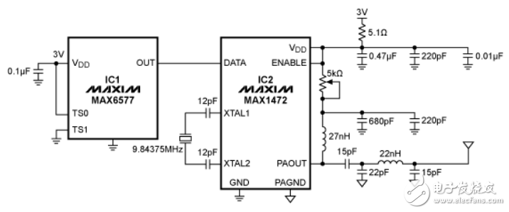
In Figure 2, the MAX1470 is the ASK receiver and demodulates the signal at the corresponding carrier frequency. The
output signal‘s frequency is measured with a frequency counter. The configured scalar multiplier is 1K/Hz when TS1 is
connected to GND and TS0 connected to VDD. This scalar multiplier is configurable with pins TS1 and TS0 (Figure 1)。
The MAX9075 is a comparator connected to the MAX1470’s RSSI with internal peak detector pin. The external RC
follows the peak power of the received signal. This is compared with a predetermined voltage level generated by a
resistor voltage divider. Lab experiments show that a threshold of approximately 1.57V generates a valid output on the
DATAOUT pin without receiving false readings. Adjust this threshold to the proper level for optimal performance. The
comparator‘s output is low when a weak or invalid signal is received and high when the received signal is adequate.
Next the MAXQ2000, a MAXQ-based microcontroller, measures the signal frequency and displays the value using its
integrated timer/counters and LCD driver peripherals. A counter tracks the number of rising-edge transitions on the input
temperature signal, while a timer tracks the elapsed time. After the timer’s 1-second period elapses, an interrupt occurs.
At this moment, the counter value is read, converted to Celsius, and displayed on the LCD. Next, the counter is reset to
0 to restart the process. The timer is automatically reloaded once the timer interrupt occurs. The resulting temperature is
also output by UART0. A handheld frequency counter is used to verify the temperature reading.
The microcontroller monitors the signal power through P6.0, configured as a general-purpose input pin. When the input is
logic low, the LCD and UART output will be “no RF” to alert the user of possible transmitter issues when the transmitter
and receiver pair is separated by too great a distance.
The LCD connection follows the design in the MAX2000 evaluation (EV) kit. To ensure that the display enables the
correct segments, the internal mapping of the display‘s seven A-to-G segments needs to be preserved. A lookup table in
the data segment of the assembly code is used for this purpose. By adding an RS-232 level converter, the UART output
can send data to a data-logging device such as a computer.

声明:本文内容及配图由入驻作者撰写或者入驻合作网站授权转载。文章观点仅代表作者本人,不代表电子发烧友网立场。文章及其配图仅供工程师学习之用,如有内容侵权或者其他违规问题,请联系本站处理。 举报投诉
- 相关下载
- 相关文章


