
资料下载

使用激光和实时警报服务的家庭安全解决方案
描述
一、简介
该项目专注于开发使用激光和实时警报服务的家庭安全解决方案。只能使用 Bolt IOT Android 应用程序通过安全设置(不触发警报),然后输入正确的密码。该项目结合使用 Bolt IOT 模块和 Arduino 以及提供消息服务的 Twilio。在以下情况下会触发警报:
- 当输入正确的密码并允许该人通过时。
- 当输入错误的密码并发出警告时。
- 当有人试图在没有输入正确密码的情况下通过时。
这样的设置可以部署在走廊和门后,以便在入侵者试图进入时触发警报。
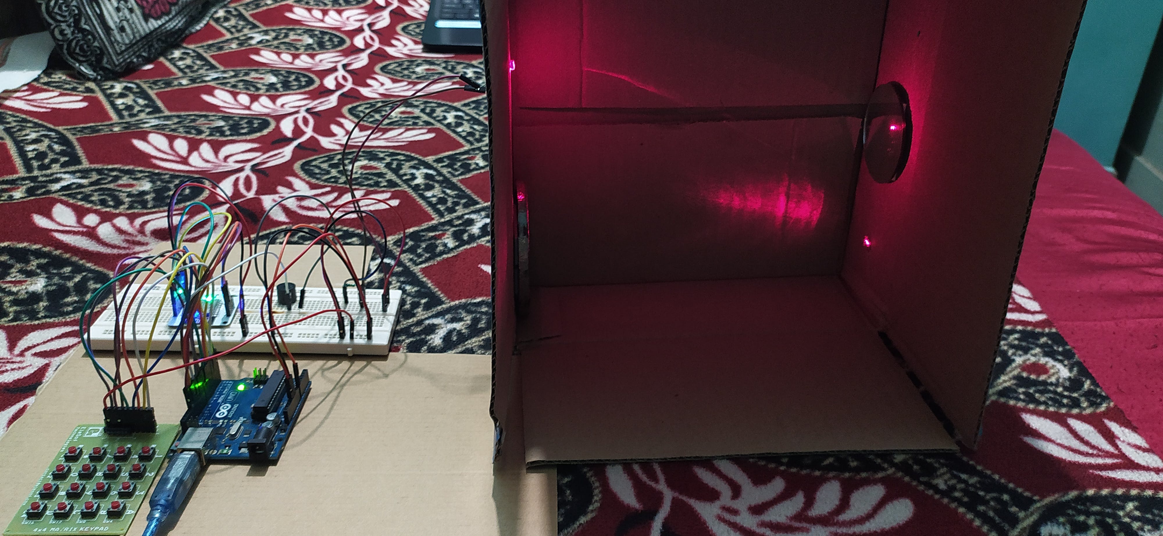

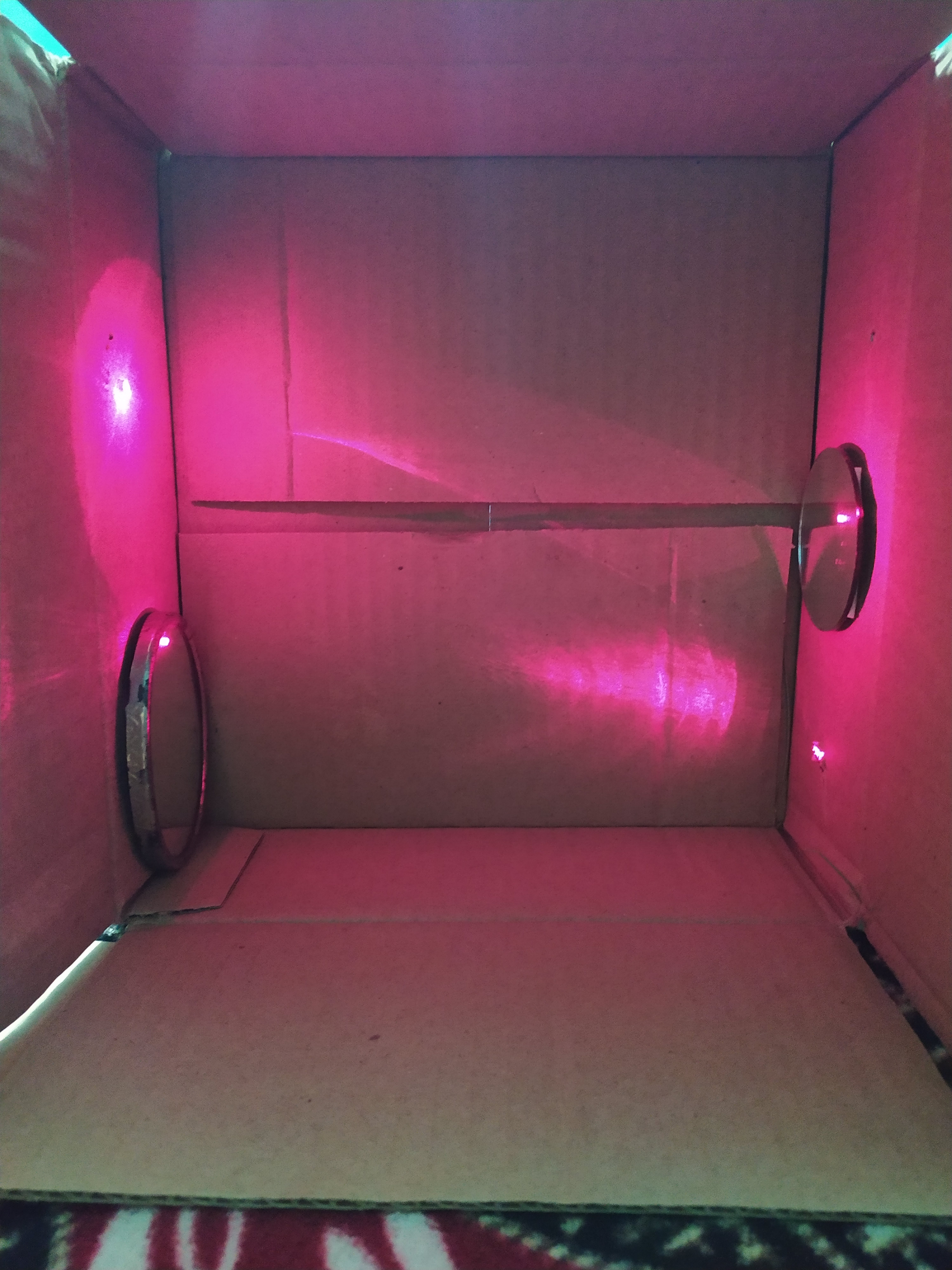
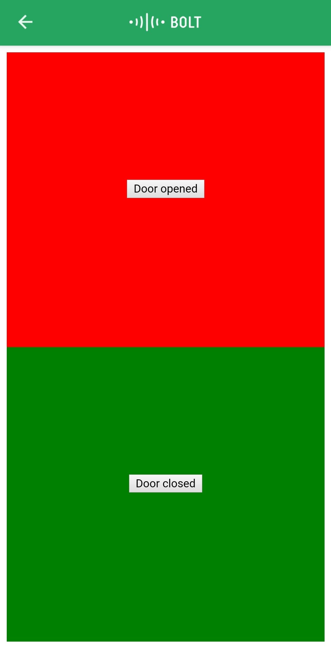
2. 示范
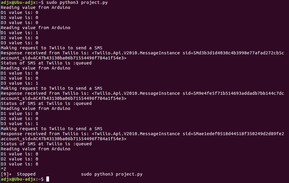


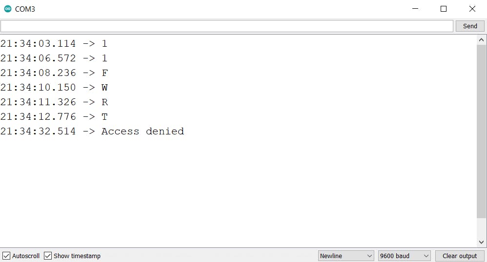

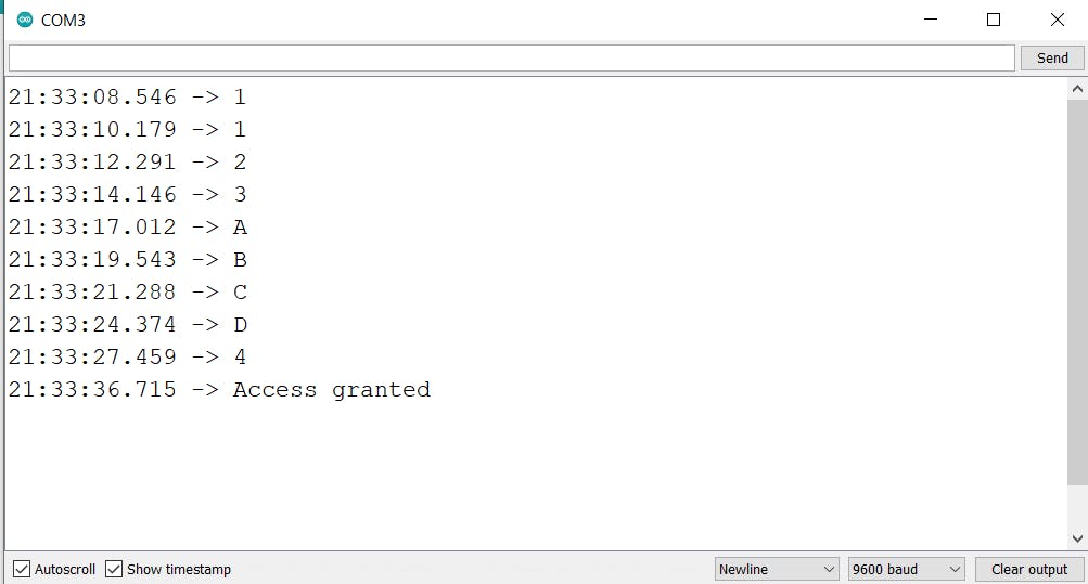
3.电路
- 3.1 组件
一世。光敏电阻 (LDR)
光敏电阻(Light Decreducing Resistance 的缩写 LDR,或光敏电阻,或 photo-con
感性电池)是一种无源组件,可降低组件敏感表面上接收光度(光)的电阻。光敏电阻的电阻随着入射光强度的增加而降低;换言之,它表现出光电导性。光敏电阻可应用于光敏检测器电路和光激活和暗激活开关电路中,作为电阻半导体。在黑暗中,光敏电阻可以具有高达几兆欧 (MΩ) 的电阻,而在光照下,光敏电阻可以具有低至几百欧姆的电阻。
压电蜂鸣器在模制外壳内包含一个压电振动板(也称为压电元件)。当施加电压并且外壳内的压电元件振动时会发出声音。
激光器是一种通过基于电磁辐射的受激发射的光学放大过程来发射光的设备。术语“激光”起源于“受激辐射的光放大”的首字母缩写词。
矩阵键盘是您在手机、计算器、微波炉、门锁等上看到的那种键盘。它们几乎无处不在。然而,在 DIY 电子产品中,它们是让用户与您的项目交互的好方法,并且经常需要导航菜单、输入密码和控制机器人

- 3.2 与 Arduino 和 Bolt IOT 模块的连接
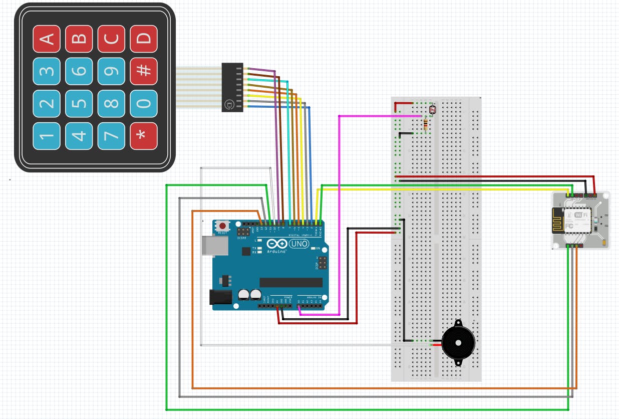
>> 将 Bolt 模块的 TX 引脚连接到 Arduino 的 Rx 引脚(引脚 0),将 Bolt 模块的 RX 引脚连接到 Arduino 的 TX 引脚(引脚 1)。还将 Bolt 模块的 5V 引脚和 GND 引脚连接到 Arduino 上的相应引脚。
>>对于 4x4 矩阵键盘,将引脚 R1 到 C4 连接到 Arduino 上的引脚 2 到引脚 9,并将 VCC 引脚(如果存在)连接到 5V。
>>将压电蜂鸣器的+引脚连接到Arduino上的引脚10。
>>将 LDR 与 1k 欧姆电阻串联连接到 5V 电源,并将电阻的另一端连接到 GND。将 LDR 和电阻的连接点连接到 Arduino 上的模拟引脚 A0。
>>将 Arduino 上的 11、12 和 13 针连接到 Bolt IOT 模块上的 1、2 和 3 针。
4.代码组件
- 4.1 Arduino代码
#include
上面的 Arduino 代码很容易理解,因为我在其中提供了注释。
请记住,在将 Arduino 代码上传到开发板时,请先移除 TX 和 RX 引脚,然后再上传,否则会出现错误。同样在输入密码时,最后按'*'结束密码。
- 4.2 HTML代码(用户界面设计)
html>
<html>
    <head>
        <title>
            Project
        title>
        <script type="text/javascript" src="https://cloud.boltiot.com/static/js/boltCommands.js">script>
        <script>
        setKey('{{ApiKey}}','{{Name}}');
        script>
    head>
    <body onload="serialBegin(9600)">
        <div style="background-color:red;height:350px;">
            <center>
                <br><br><br><br><br><br><br><br>
                <button onclick="serialWrite('1')">Door openedbutton>
            center>
        div>
        <div style="background-color:green;height:350px;">
            <center>
                <br><br><br><br><br><br><br><br>
                <button onclick="serialWrite('0')">Door closedbutton>
            center>
        div>
    body>
html>
源链接向浏览器提供了“serialBegin()”和“serialWrite()”的定义。

- 4.3 Python代码
该项目的 python 编码已在 Ubuntu (Linux) 中完成。在我们开始用 python 编写主代码文件之前,我们需要制作一个配置文件,其中包含每个用户/设备的特定密钥。我们将在我们的主代码中导入这个文件并使用各种属性。这样做的好处是每个用户只需更改配置文件的内容即可使用该产品。
以下是配置文件(命名为 conf.py):
sid = 'You can find SID in your Twilio Dashboard'
auth_token = 'You can find  on your Twilio Dashboard'
from_number = 'This is the no. generated by Twilio. You can find this on your Twilio Dashboard'
to_number = 'This is your number. Make sure you are adding +91 in beginning'
api_key = 'This is your Bolt Cloud accout API key'
device_id = 'This is the ID of your Bolt device'
Bolt 模块的 API 密钥和设备 ID 可以如下确定:
>>按照https://cloud.boltiot.com/ 上的说明将您的 Bolt 设备连接到 Bolt Cloud。
>>之后将出现以下屏幕。螺栓设备 ID 以黄色突出显示。
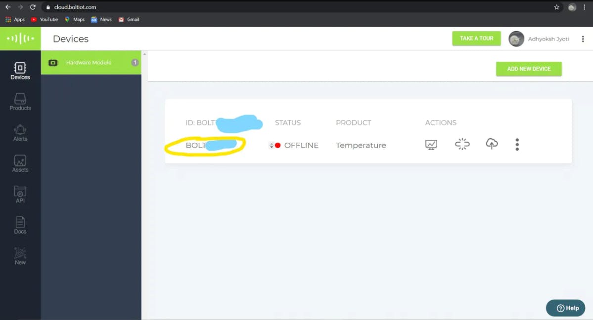
>>转到API部分以了解API Key。
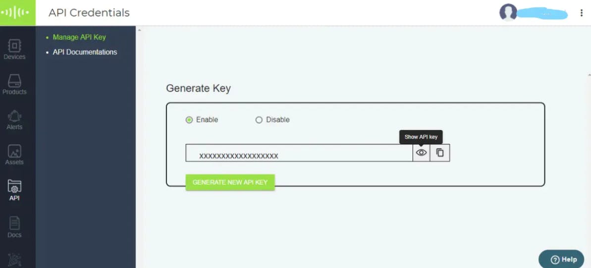
<>创建 Twilio 帐户
第 1 步:在浏览器中打开https://www.twilio.com/ 。
第二步:点击Get a Free API Key按钮注册。
第 3 步:在注册表格中填写所有必要的详细信息。下面是填写好的注册表单的截图。
第 4 步:为了验证他们会询问您的电话号码。在下拉列表中选择印度作为选项,然后输入您的电话号码。
第 5 步:选择“可编程短信”选项。
第 6 步:您可以在此页面上查看 Account SID 和 Auth token。Auth 令牌默认不可见,您可以单击“查看”按钮使 Auth 令牌可见,如下图所示。复制两者并将它们安全地保存在某个地方。
第七步:点击Get a number按钮。
第8步:然后会出现一个弹出窗口。点击Choose this number按钮。
第9步:然后会出现一个弹出窗口,其中将包含最终数字。复制此编号并保存到记事本以供将来参考。
**完整的Python代码
import conf
from boltiot import Sms, Bolt
import json, time


mybolt = Bolt(conf.api_key, conf.device_id)
sms = Sms(conf.sid, conf.auth_token, conf.to_no, conf.from_no)


while True:
    print ("Reading value from Arduino")
    resp1 = mybolt.digitalRead('1')
    d1 = json.loads(resp1)
    resp2 = mybolt.digitalRead('2')
    d2 = json.loads(resp2)
    resp3 = mybolt.digitalRead('3')
    d3 = json.loads(resp3)
    print("D1 value is: " + str(d1['value']))
    print("D2 value is: " + str(d2['value']))
    print("D3 value is: " + str(d3['value']))
    try:
       sens1 = int(d1['value'])
       sens2 = int(d2['value'])
       sens3 = int(d3['value'])
       if sens3 == 1 :
             print("Making request to Twilio to send a SMS")
             response = sms.send_sms("Breach!!!! Someone has entered forcefully.")
             print("Response received from Twilio is: " + str(response))
             print("Status of SMS at Twilio is :" + str(response.status))
       elif sens2 == 1 :
             print("Making request to Twilio to send a SMS")
             response = sms.send_sms("Someone is trying to open the door.")
             print("Response received from Twilio is: " + str(response))
             print("Status of SMS at Twilio is :" + str(response.status))
       elif sens1 == 1 :
             print("Making request to Twilio to send a SMS")
             response = sms.send_sms("The door is opened. You can enter now.")
             print("Response received from Twilio is: " + str(response))
             print("Status of SMS at Twilio is :" + str(response.status))

    except Exception as e:
       print ("Error occured: Below are the details")
       print (e)
    time.sleep(10)
在上面的 python 代码中,d1、d2 和 d3 是 Bolt IOT 模块从 Arduino 接收到的输入值。
5. 要记住的要点
一世。将 Arduino 代码上传到开发板时,请先移除 TX 和 RX 引脚,然后再上传,否则会出现错误。
ii. 输入密码时,最后按“*”结束密码。
iii. 进入后,请记住按 Bolt IOT Android 应用程序上的“关门”按钮。
声明:本文内容及配图由入驻作者撰写或者入驻合作网站授权转载。文章观点仅代表作者本人,不代表电子发烧友网立场。文章及其配图仅供工程师学习之用,如有内容侵权或者其他违规问题,请联系本站处理。 举报投诉
- 相关下载
- 相关文章


