
资料下载


×
如何驱动数码管
消耗积分:2 |
格式:zip |
大小:0.10 MB |
2022-12-19
刘丰标
分享资料个
描述
我们需要的
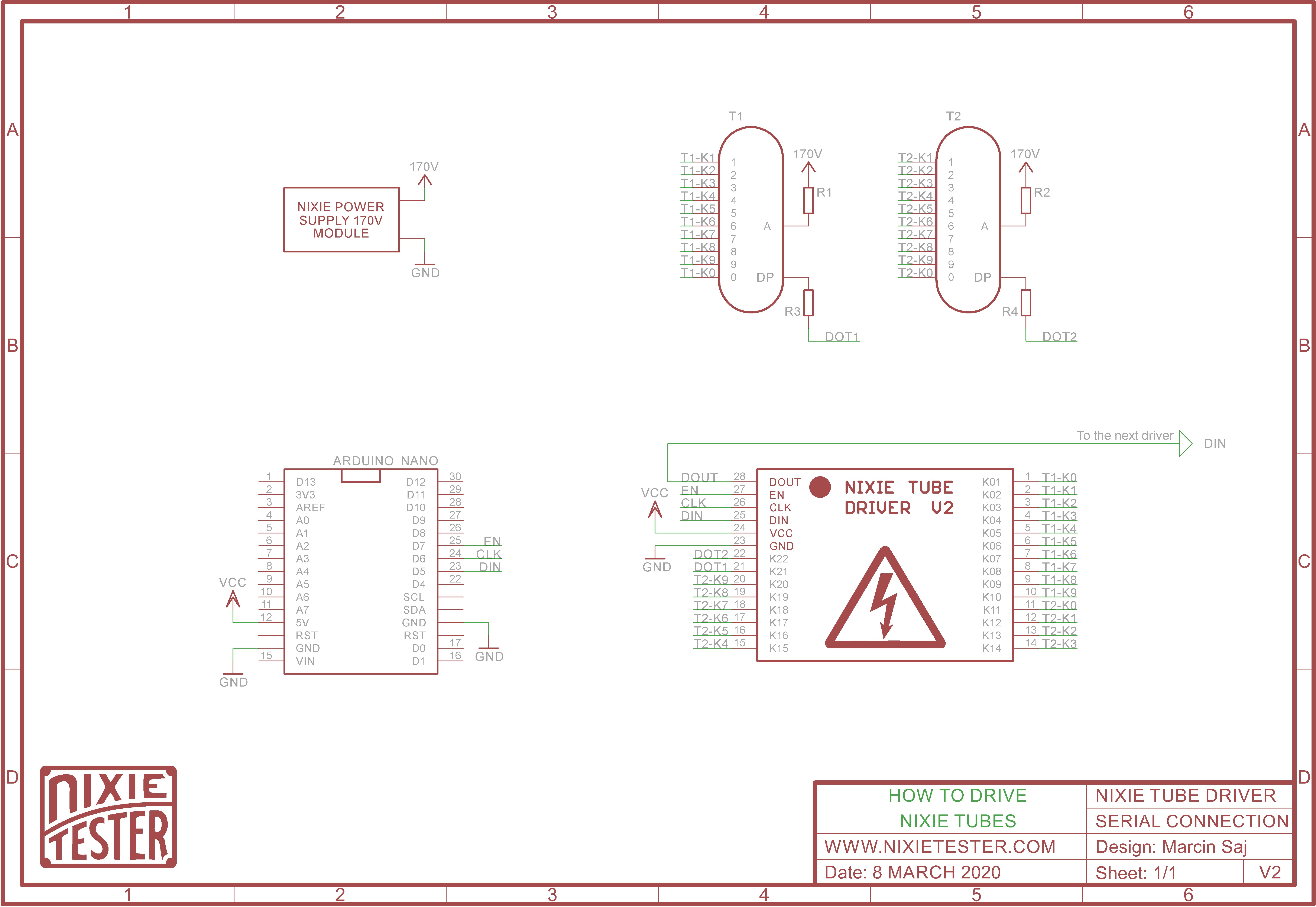
- 数码管需要 170V 直流电源,所以我们需要数码管电源模块 - 任何高压 170V 转换器都可以。
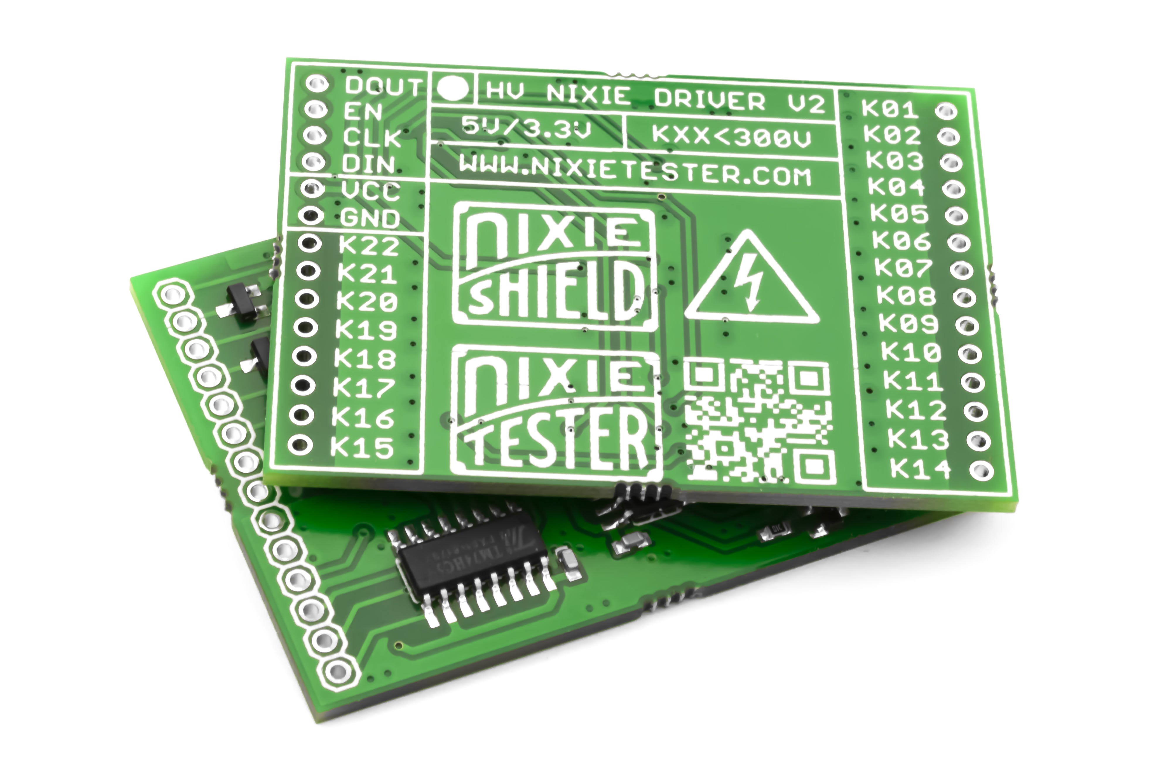
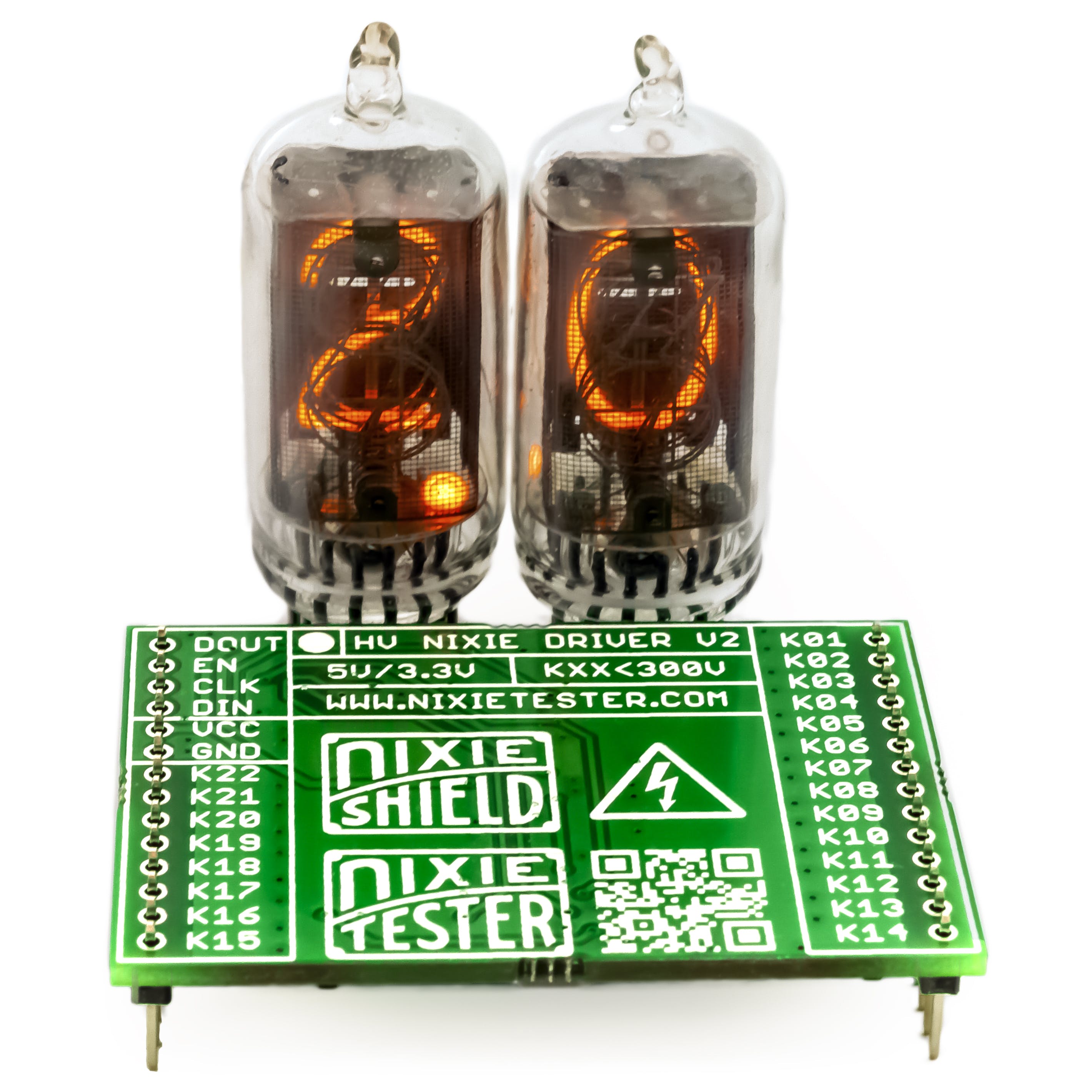
- 我们需要一个适用于高压的驱动器 - 例如Nixie Tube Driver V2
- 任何 Arduino 板 - 在本例中,它将是 Arduino Nano
1 / 2
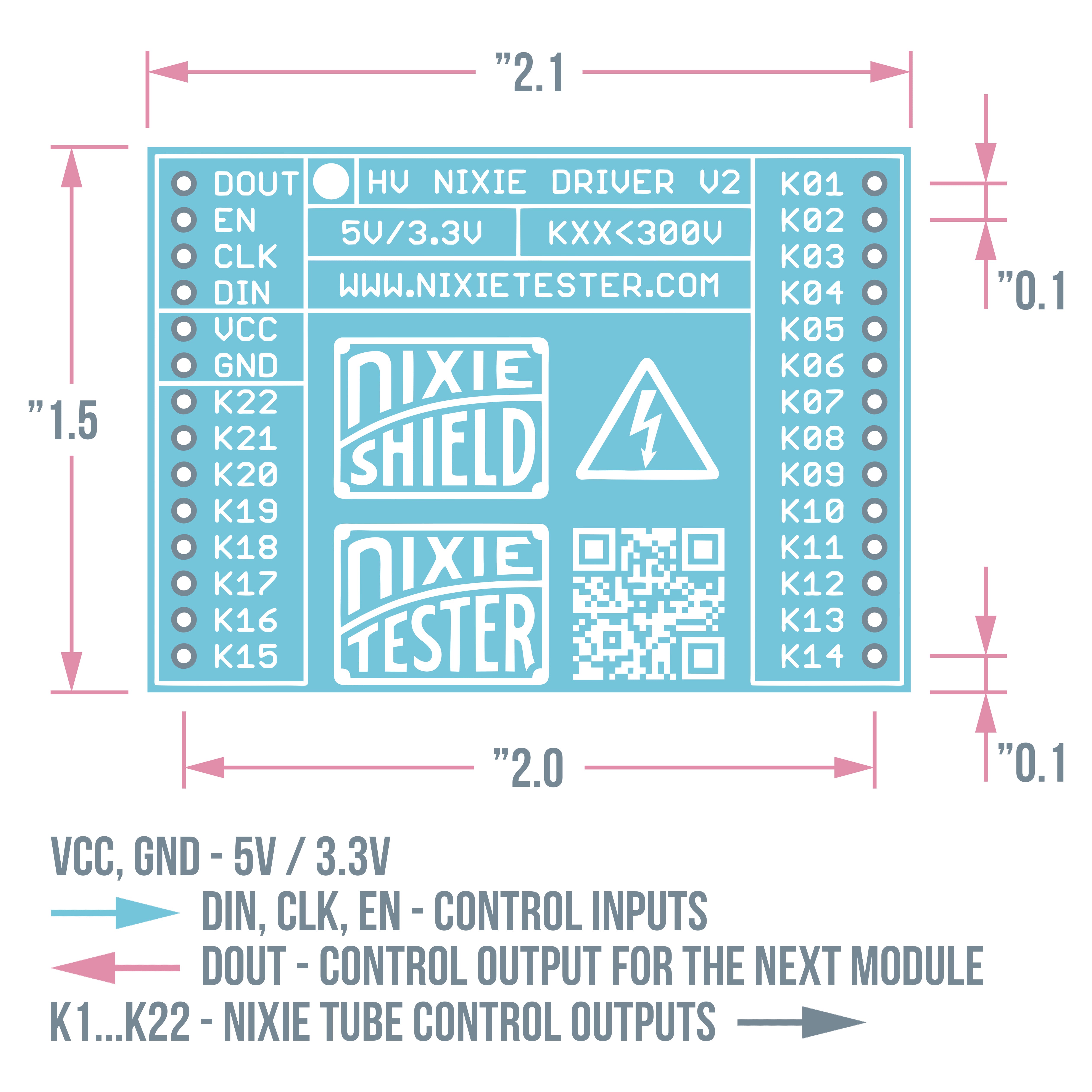
数码管驱动器 V2 - 参数
- 22路输出连接数码管阴极(K1-K22)
- 300V 关态最大输出电压
- 兼容所有 5V / 3.3V 设计
- 易于使用 - 只有 3 条控制线
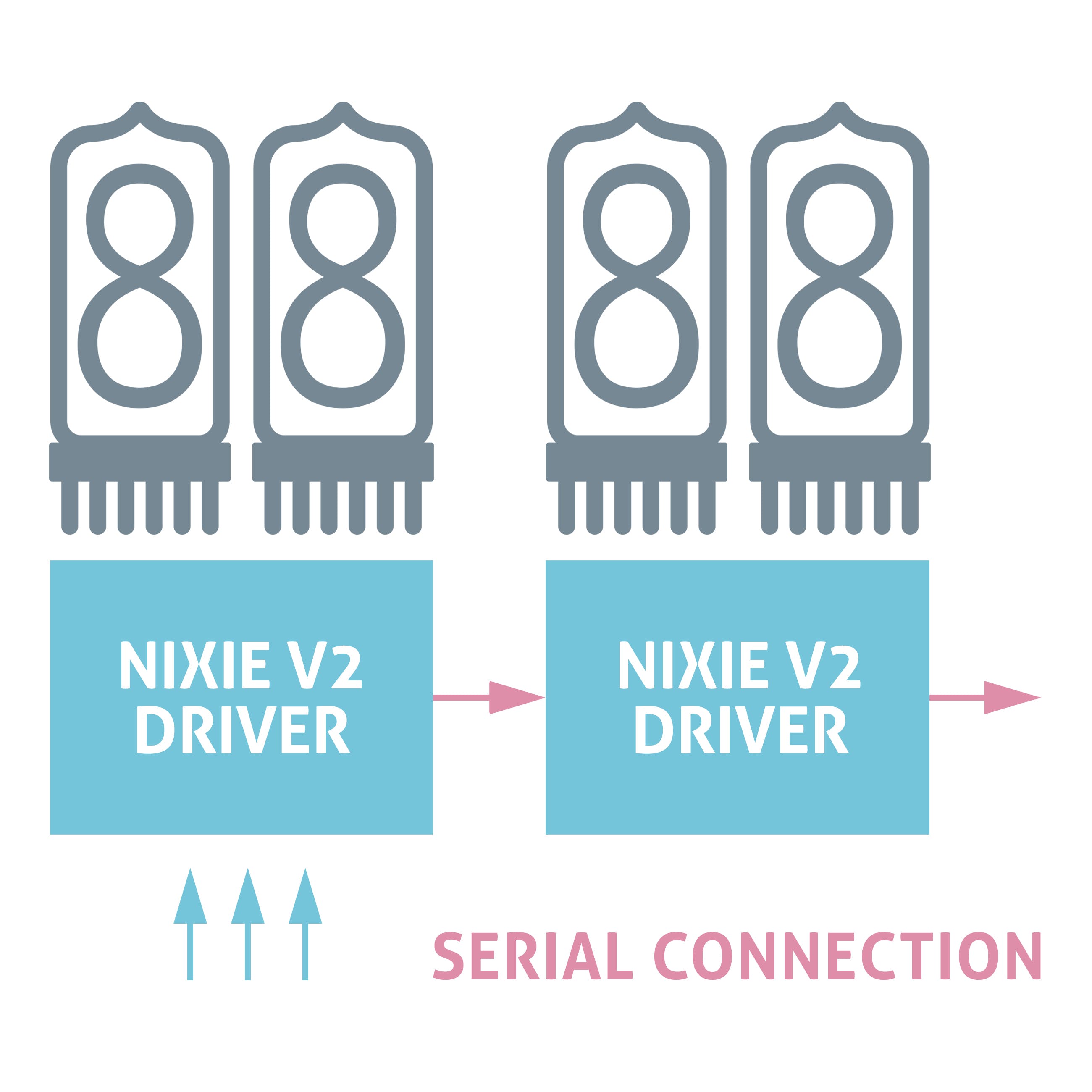
- 驱动器可以串联
有关 Nixie Tube Driver V2 的更多信息,请访问项目网站。
如何将数码管连接到驱动器
只有 3 条控制线 DIN、CLK、EN。22路输出让您可以连接两个带点的数码管
阿杜诺代码
一开始我们必须声明我们是如何连接各个数码管阴极的:
// Bit array for 2 nixie tubes, dot1, dot2, 2 bits for gaps
boolean nixieDisplayArray[24];

// Cathodes assignment to the position in the 24 bit array
// Each cathode of nixie tubes is connected to the corresponding driver output

// Bit numbers
byte nixie1[]={
//   0   1   2   3   4   5   6   7   8   9
0,  1,  2,  3,  4,  5,  6,  7,  8,  9 };
byte nixie2[]={
//   0   1   2   3   4   5   6   7   8   9
10, 11, 12, 13, 14, 15, 16, 17, 18, 19 };
byte dot1 = 20;   // K21 nixie driver output
byte dot2 = 21;   // K22
nixieDisplayArray[24]; 如果驱动器有 22 个输出,为什么是 24 位?如果您仔细查看数码驱动器的内部原理图,您会注意到其中一个移位寄存器有两个未连接的输出。如果我们想使用多个串联的驱动程序,我们必须填补这个空白,以便将数据正确传输到后续驱动程序(寄存器)。
移位寄存器控制程序。您还可以使用任何库来控制移位寄存器,但为了更好地理解该程序包含控制寄存器所需的所有步骤,而无需使用该库。
void ShiftOutData()
{
// Ground EN pin and hold low for as long as you are transmitting
digitalWrite(EN_PIN, 0);
// Clear everything out just in case to
// prepare shift register for bit shifting
digitalWrite(DIN_PIN, 0);
digitalWrite(CLK_PIN, 0);
// Send data to the nixie drivers
for (int i = 23; i >= 0; i--)
{
// Set high only the bit that corresponds to the current nixie digit
digitalWrite(DIN_PIN, nixieDisplayArray[i]);
// Register shifts bits on upstroke of CLK pin
digitalWrite(CLK_PIN, 1);
// Set low the data pin after shift to prevent bleed through
digitalWrite(CLK_PIN, 0);
}
// Return the EN pin high to signal chip that it
// no longer needs to listen for data
digitalWrite(EN_PIN, 1);
// Stop shifting
digitalWrite(CLK_PIN, 0);
}
核心控制代码:
void NixieDisplay(byte digit1, byte digit2)
{
// Convert the desired numbers to the bit numbers for the nixieDisplayArray[]
digit1 = nixie1[digit1];
digit2 = nixie2[digit2];
// Clear bit array except dot1 and dot2 bits
for (int i = 23; i >= 0; i--)
{
if(i != dot1 || i != dot2) nixieDisplayArray[i] = 0;
}
// Set the bits corresponding to the nixie tubes cathodes
nixieDisplayArray[digit1] = 1;
nixieDisplayArray[digit2] = 1;
ShiftOutData();
}
nixieDisplayArray[] - 这是一个存储所有 nixie 控制器输出当前状态的位数组。如果要独立控制管和点,则需要存储输出的当前状态。
// SetDot (dotNumber = 1/2, dotState = 0/1)
void SetDot(byte dotNumber, boolean dotState)
{
if(dotNumber == 1)
{
if(dotState == HIGH) nixieDisplayArray[dot1] = 1;
else nixieDisplayArray[dot1] = 0;
}
if(dotNumber == 2)
{
if(dotState == HIGH) nixieDisplayArray[dot2] = 1;
else nixieDisplayArray[dot2] = 0;
}
ShiftOutData();
}
如何显示“2.0”
现在最后一步是最简单的部分:
void loop ()
{
// NixieDisplay(digit1, digit2);
NixieDisplay(2, 0);
// SetDot (dotNumber = 1/2, dotState = 0/1)
SetDot(1, HIGH);
delay(1000);
}
1 / 2
声明:本文内容及配图由入驻作者撰写或者入驻合作网站授权转载。文章观点仅代表作者本人,不代表电子发烧友网立场。文章及其配图仅供工程师学习之用,如有内容侵权或者其他违规问题,请联系本站处理。 举报投诉
评论(0)
发评论
- 相关下载
- 相关文章


