资料下载

×
适用于PC的ARDUINO控制游戏手柄(有线)
消耗积分:2 |
格式:zip |
大小:2.29 MB |
2022-12-20
描述
大家好,我是 Sarvesh。几天前,我想玩一些复古游戏。所以我把它们安装在我的电脑上。但我只能用我的电脑键盘玩,这并没有给我童年时代的感觉。所以我决定为我的 PC 构建一个可以玩旧游戏和新游戏(不是全部)的游戏手柄。我使用了一个旧的游戏控制器并对其进行了修改以创建这个很棒的游戏手柄。这是一款用于 PC 的有线游戏手柄。它可以用来玩模拟器和PC游戏。此外,操纵杆还可以用作 PC 的鼠标。游戏手柄使用 Arduino Pro Micro 进行控制。
第 1 步:电路图和按键映射


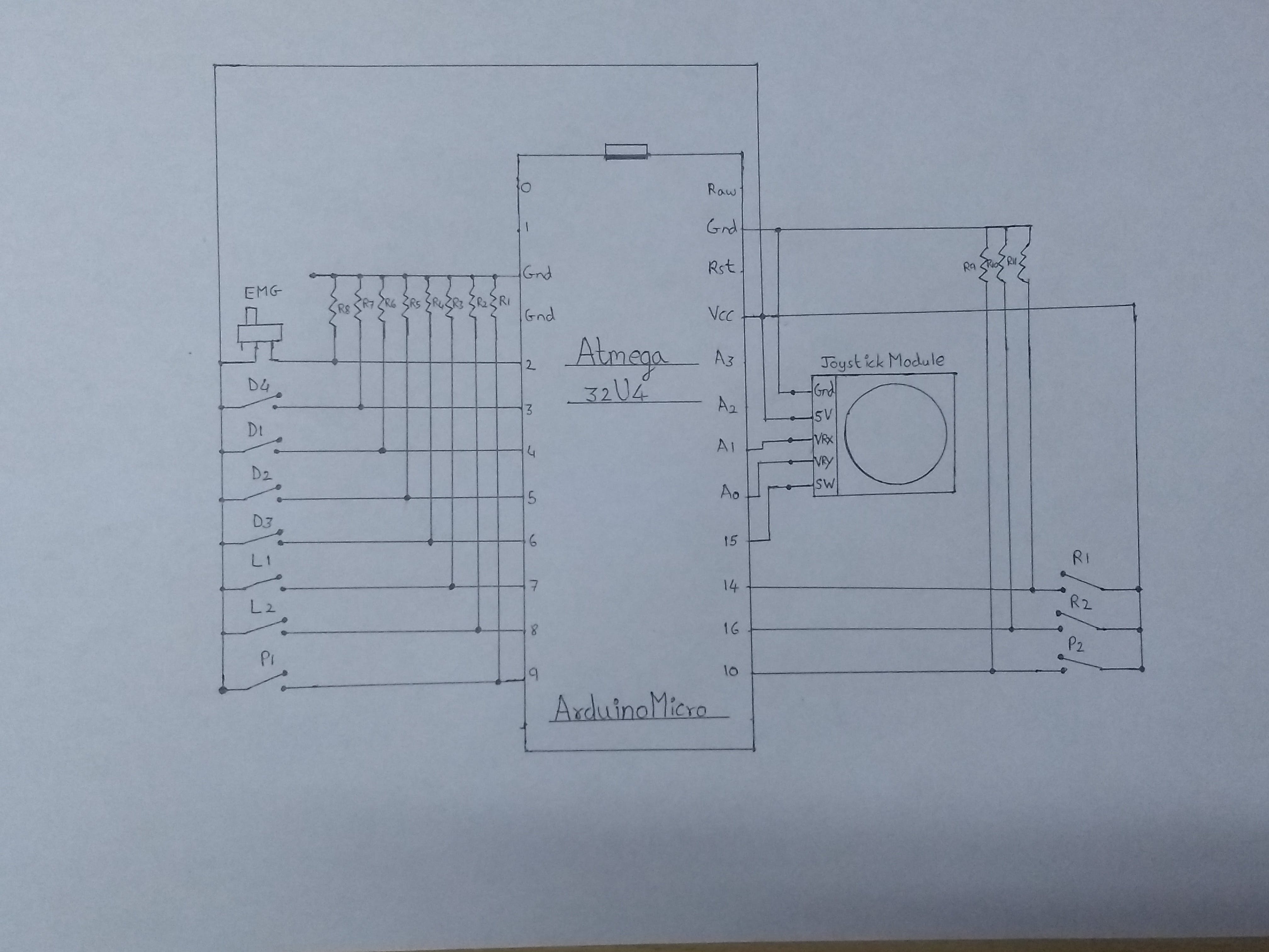
根据上面给出的电路图(第一个图像)连接所有组件。
我建议首先检查所有连接并在面包板上工作。
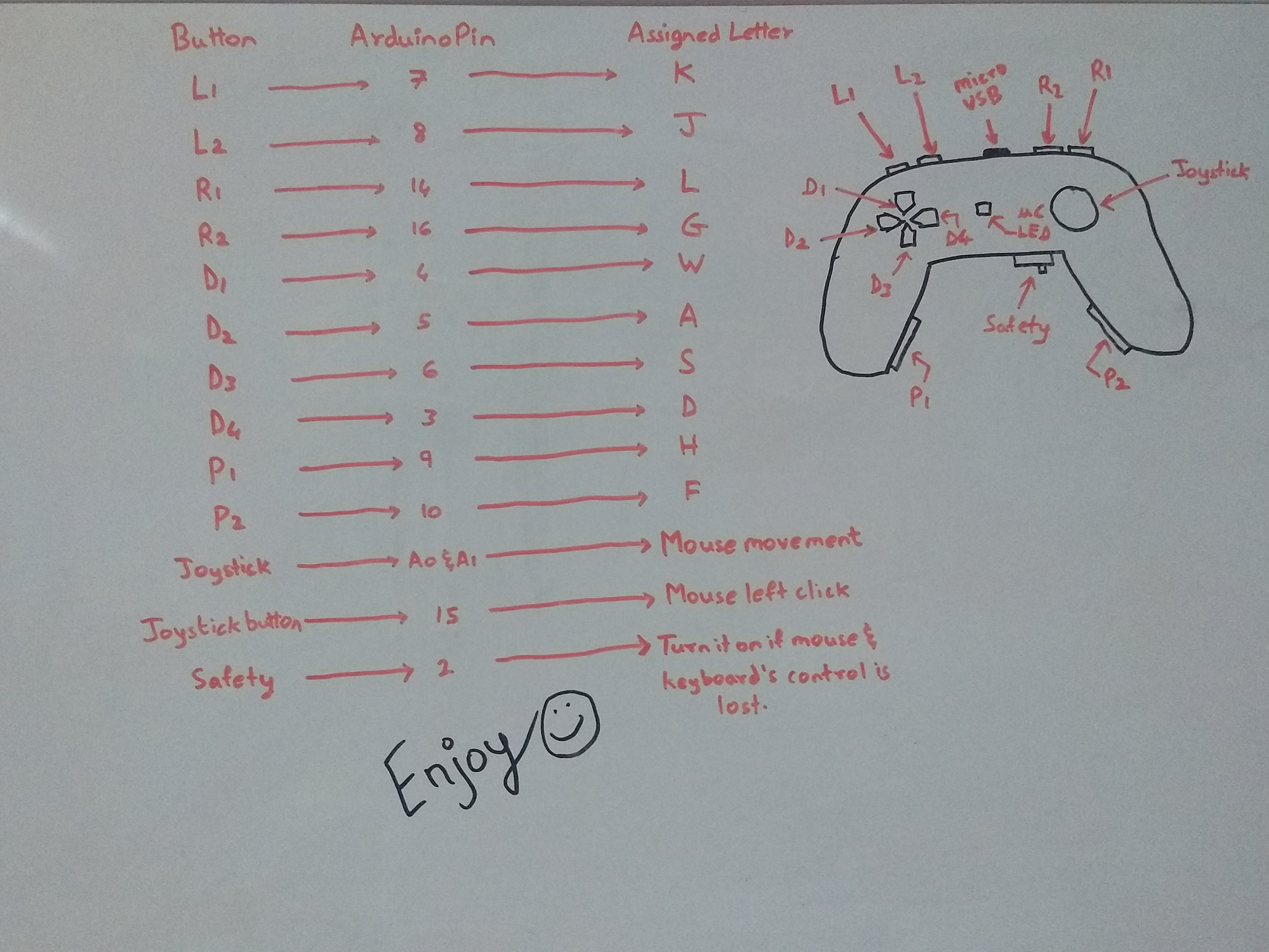
按键映射:
我实际按钮放置的布局也显示在上面(第二张图片),让您清楚地知道哪个按钮位于何处,它使用什么标签编程以及它向计算机发送什么字符。
第 2 步:Arduino 代码
现在下载代码并安装 mouse.h 和 keyboard.h 库。将代码上传到您的 Arduino。
您可以从下面复制代码。
#include
#include
const int EMG = 2;    //Emergency stop button :)
const int L1 = 7;
const int L2 = 8;
const int P1 = 9;
const int R1 = 14;
const int R2 = 16;
const int P2 = 10;
const int D1 = 4;
const int D2 = 5;
const int D3 = 6;
const int D4 = 3;
const int SWITCH = 15; // digital pin 2 connected to SW output of JoyStick
const int X_AX = A1; // analog pin 0 connected to X output of JoyStick
const int Y_AX = A0; // analog pin 1 connected to Y output of JoyStick
int range = 10;               // output range or speed of X or Y movement
int responseDelay = 5;        // response delay of the mouse, in ms
int threshold = range / 4;    // resting threshold
int center = range / 2;
int EMGState = HIGH;
int L1S = LOW;
int L2S = LOW;
int P1S = LOW;
int R1S = LOW;
int R2S = LOW;
int P2S = LOW;
int D1S = LOW;
int D2S = LOW;        //PREVIOUS STATES
int D3S = LOW;
int D4S = LOW;
void setup()
{
  pinMode(EMG, INPUT);
  pinMode(L1, INPUT);
  pinMode(L2, INPUT);
  pinMode(P1, INPUT);
  pinMode(D1, INPUT);
  pinMode(D2, INPUT);
  pinMode(D3, INPUT);
  pinMode(D4, INPUT);
  pinMode(R1, INPUT);
  pinMode(R2, INPUT);
  pinMode(P2, INPUT);
  pinMode(SWITCH, INPUT_PULLUP);
  Serial.begin(9600);
  Keyboard.begin();
  Mouse.begin();
}

void loop()
{

  EMGState = digitalRead(EMG);
  if (EMGState == HIGH)
  {
    Serial.println("FAULT");
    Keyboard.releaseAll();
    Keyboard.end();
    Mouse.end();
  }
  else
  {
      //Serial.println("OK");
      int L1STATE = digitalRead(L1);
      int L2STATE = digitalRead(L2);
      int P1STATE = digitalRead(P1);
      int D1STATE = digitalRead(D1);
      int D2STATE = digitalRead(D2);
      int D3STATE = digitalRead(D3);
      int D4STATE = digitalRead(D4);
      int R1STATE = digitalRead(R1);
      int R2STATE = digitalRead(R2);
      int P2STATE = digitalRead(P2);

      if(L1STATE==HIGH && L1S == LOW)
      {
        Serial.println("L1 PRESSED");
        Keyboard.press('K');              //K
      }
      if(L1STATE==LOW && L1S == HIGH)
      {
        Serial.println("L1 RELEASED");
        Keyboard.release('K');              //K
      }


      if(L2STATE==HIGH && L2S == LOW)
      {
        Serial.println("L2 PRESSED");
        Keyboard.press('J');              //J
      }
      if(L2STATE==LOW && L2S == HIGH)
      {
        Serial.println("L2 RELEASED");
        Keyboard.release('J');              //J
      }


      if(P1STATE==HIGH && P1S == LOW)
      {
        Serial.println("P1 PRESSED");
        Keyboard.press('H');              //H
      }
      if(P1STATE==LOW && P1S == HIGH)
      {
        Serial.println("P1 RELEASED");
        Keyboard.release('H');              //H
      }

      if(R1STATE==HIGH && R1S == LOW)
      {
        Serial.println("R1 PRESSED");     //L
        Keyboard.press('L');
      }
      if(R1STATE==LOW && R1S == HIGH)
      {
        Serial.println("R1 RELEASED");     //L
        Keyboard.release('L');
      }

      if(R2STATE==HIGH && R2S == LOW)
      {
        Serial.println("R2 PRESSED");     //G
        Keyboard.press('G');
      }
      if(R2STATE==LOW && R2S == HIGH)
      {
        Serial.println("R2 RELEASED");     //G
        Keyboard.release('G');
      }

      if(P2STATE==HIGH && P2S == LOW)
      {
        Serial.println("P2 PRESSED");     //F
        Keyboard.press('F');
      }
      if(P2STATE==LOW && P2S == HIGH)
      {
        Serial.println("P2 RELEASED");     //F
        Keyboard.release('F');
      }


      if(D1STATE==HIGH && D1S == LOW)
      {
        Serial.println("D1 PRESSED");     //W
        Keyboard.press('W');
      }
      if(D1STATE==LOW && D1S == HIGH)
      {
        Serial.println("D1 RELEASED");     //W
        Keyboard.release('W');
      }


      if(D2STATE==HIGH && D2S==LOW)
      {
        Serial.println("D2 PRESSED");     //A
        Keyboard.press('A');
      }
      if(D2STATE==LOW && D2S==HIGH)
      {
        Serial.println("D2 RELEASED");     //A
        Keyboard.release('A');
      }


      if(D3STATE==HIGH && D3S==LOW)
      {
        Serial.println("D3 PRESSED");     //S
        Keyboard.press('S');
      }
      if(D3STATE==LOW && D3S==HIGH)
      {
        Serial.println("D3 RELEASED");     //S
        Keyboard.release('S');
      }


      if(D4STATE==HIGH && D4S==LOW)
      {
        Serial.println("D4 PRESSED");     //D
        Keyboard.press('D');
      }
      if(D4STATE==LOW && D4S==HIGH)
      {
        Serial.println("D4 RELEASED");     //D
        Keyboard.release('D');
      }

      L1S = L1STATE;
      L2S = L2STATE;
      P1S = P1STATE;
      R1S = R1STATE;
      R2S = R2STATE;
      P2S = P2STATE;
      D1S = D1STATE;
      D2S = D2STATE;
      D3S = D3STATE;
      D4S = D4STATE;


     int xReading = readAxis(A1);
     int yReading = readAxis(A0);
     Mouse.move(xReading, yReading, 0);
     if (digitalRead(SWITCH) == LOW)
       {
         if (!Mouse.isPressed(MOUSE_LEFT))
         {
           Mouse.press(MOUSE_LEFT);
         }
       }
      else
      {
      if (Mouse.isPressed(MOUSE_LEFT))
      {
        Mouse.release(MOUSE_LEFT);
      }
      }

        delay(responseDelay);
 }
}
int readAxis(int thisAxis)
{
  int reading = analogRead(thisAxis);
  reading = map(reading, 0, 1023, 0, range);
  int distance = reading - center;
  if (abs(distance) < threshold)
  {
    distance = 0;
  }

  return distance;
}
第 3 步:切割、绘画和焊接
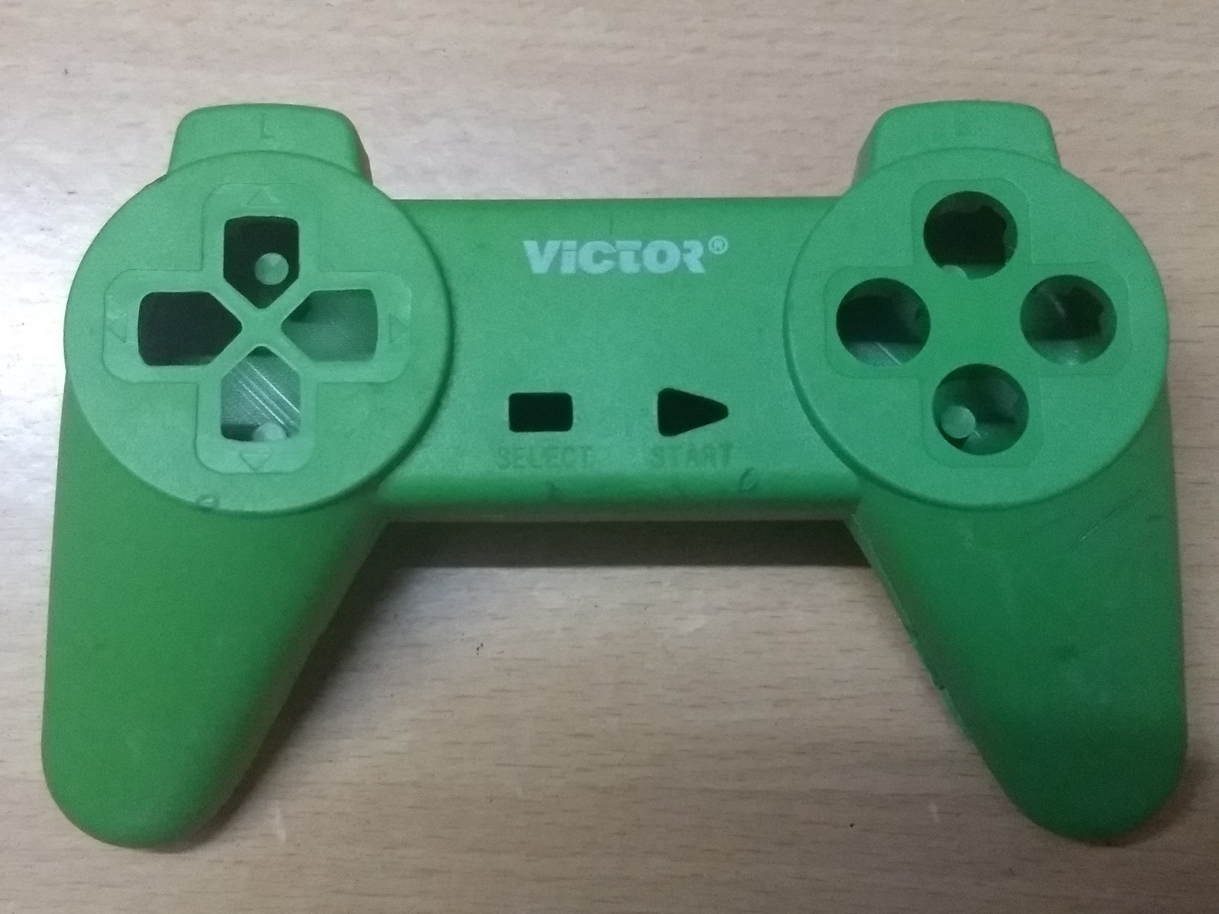
首先根据游戏手柄的尺寸切割 PCB 并将按钮和操纵杆模块对齐。
然后用你选择的颜色给游戏手柄上漆。
现在将按钮和操纵杆焊接到通用 pcb 上。
然后借助一些强力胶将限位开关固定在它们的位置。
焊接其余组件并进行最终测试。
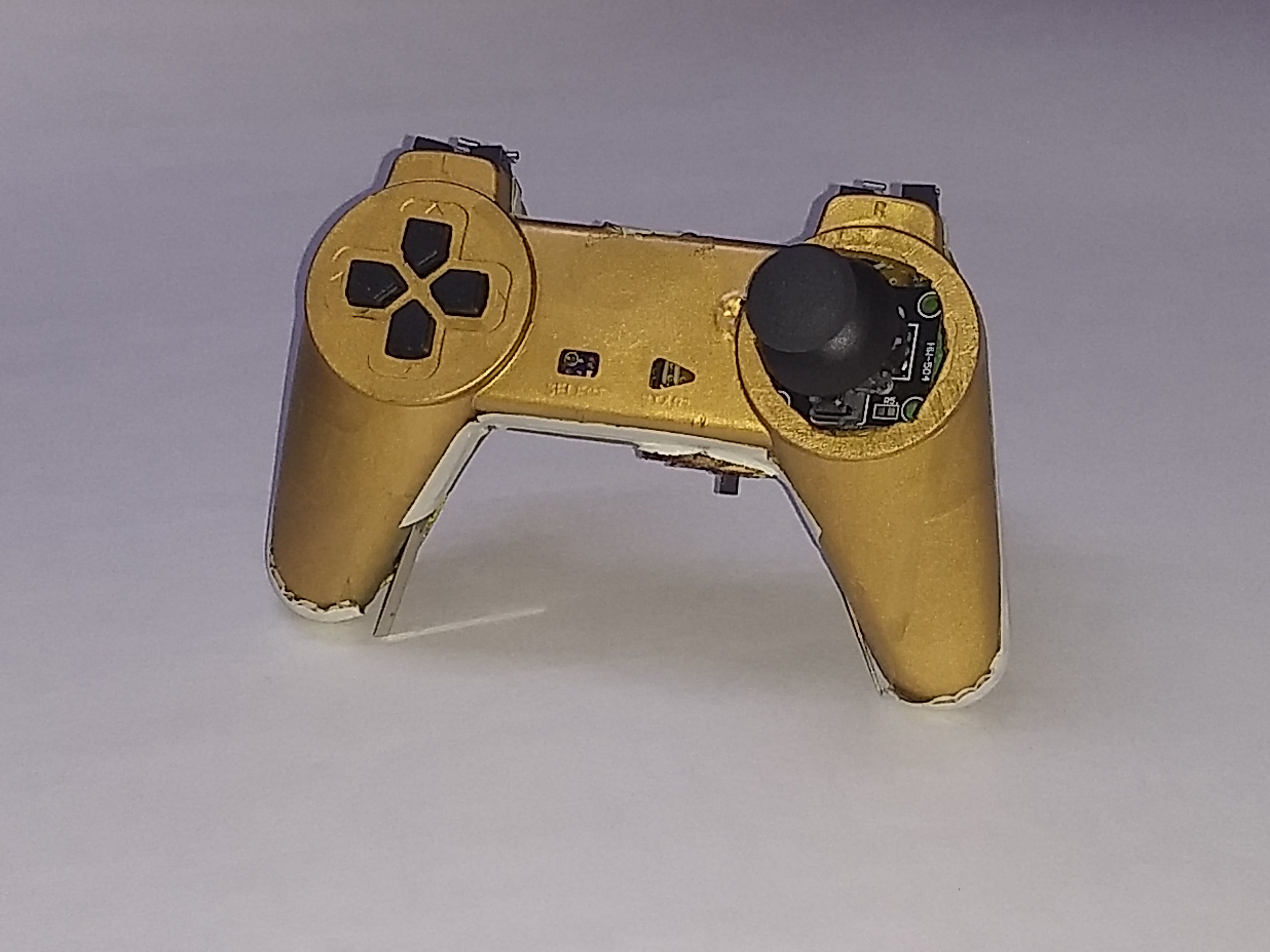
我附上了下面的图片以供参考。

1 / 6
这是最终项目的样子。

声明:本文内容及配图由入驻作者撰写或者入驻合作网站授权转载。文章观点仅代表作者本人,不代表电子发烧友网立场。文章及其配图仅供工程师学习之用,如有内容侵权或者其他违规问题,请联系本站处理。 举报投诉
评论(0)
发评论
- 相关下载
- 相关文章


