
资料下载

易于使用的动力假肢开源分享
描述
一种易于使用的动力假肢——开源且价格合理。为适应持续发展而开发的简单、有效、辅助技术。由一群勤奋的本科生为您带来,他们热衷于机器人技术被广泛用于改善所有人生活质量的未来愿景。虽然新技术的努力往往是挥霍无度的,但我们的腿的成本大约相当于一张中档宜家沙发(550 美元)。
我们的项目和价格点在很大程度上依赖于新技术的利用,例如最近才出现的连续 3D 打印碳纤维。此外,我们的项目是完全开源的,因此学生、技术爱好者和截肢者都可以自由制造和完善它。我们希望该项目能够立即提高感兴趣的截肢者的功能质量,并最终可能成为辅助技术领域扩散发展和未来研究的平台。
信用到期的信用
该项目由犹他大学的Tommaso Lenzi 博士提出概念。这些材料全部由他的实验室仿生工程实验室赞助。去尤特斯。

收集零件
要做的第一件事是订购所有组件。他们需要几天时间才能到达。我们已尝试使用尽可能少的供应商,以避免不得不进行数十次采购。
拆卸钻头
该项目使用钻头,因为它是获得强大的无刷直流电机、电机控制器、行星齿轮组和可充电锂离子电池的一种经济高效的方式。
3D打印
首选的 3D 打印机是 Markforged Mark Two,因为它能够结合连续的碳纤维束,而 Ultimaker S5 则适用于 Tough PLA 组件。
我们用连续股碳纤维打印轴套连接器,以实现令人难以置信的 3D 打印重量强度比。前壳、后壳和电机外壳采用坚固的 PLA 印刷,用于初始原型制作,以降低成本并为这些组件设定基准。随着我们继续开发,将探索使用 3D 复合打印机进行实验以减轻重量并提高这些组件的耐用性。
总共需要制作六个打印文件:
- 轴套接头(碳纤维/玛瑙复合材料)
- 前壳(Tough PLA)
- 后壳(Tough PLA)
- 电机外壳(Tough PLA)
- 垫片(Tough PLA)
- 紧急停止(Tough PLA)
轴套连接器
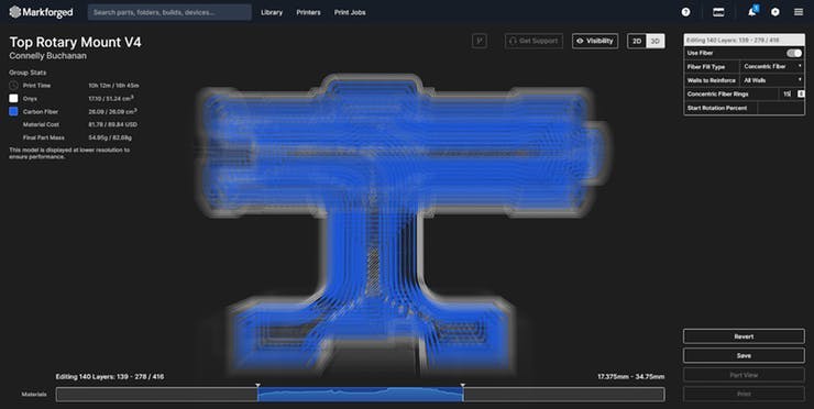
使用具有以下设置的 Markforged Mark Two 或其他复合打印机
- 喷嘴尺寸:标准
- 打印层高:0.125 [mm]
- 支持:玛瑙
- 填充率:37%
- 碳纤维同心层数:最多 15 个同心环,所有墙壁都经过加固,37% 填充,屋顶和地板层 5,墙层 3,三角形填充
- 层数:在第 139 - 278 层上加固,在所示尺寸中同心
前壳、后壳和电机外壳
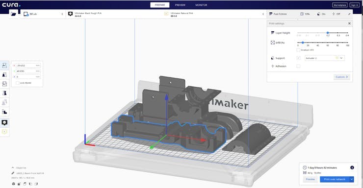
使用具有以下设置的 Ultimaker S5 或其他 Tough PLA 打印机
- 喷嘴尺寸:AA 0.4
- 印刷层高:0.2[mm]
- 支持:PVA
- 填充率:10%
垫片
使用具有以下设置的 Ultimaker S5 或其他 Tough PLA 打印机
- 喷嘴尺寸:AA 0.4
- 印刷层高:0.1[mm]
- 支持:PVA
- 填充率:100%
紧急停止
使用具有以下设置的 Ultimaker S5 或其他 Tough PLA 打印机
- 喷嘴尺寸:AA 0.4
- 印刷层高:0.06[mm]
- 支持:PVA
- 填充率:100%
电子组装
组装电路板:
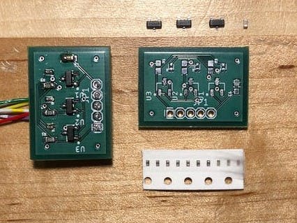
在等待零件进来的同时,您需要订购两块印刷电路板 (PCB)。一个用于主板,另一个用于地面反作用力 (GRF) 传感器。您需要将 Gerber 文件发送到您最喜欢的制造厂。压缩的 Gerber 文件可以在 GitHub 存储库上找到,文件路径为“PCB -> Motherboard”和“PCB -> GRF”。随订单一起提交 .zip 文件。我们的董事会使用了以下细节:
- 层数:2
- 材质:FR4
- 材料厚度:0.062 [英寸]
- 单位尺寸:0.972 x 2.350 [in](主板)和 0.835 x 0.600 [in](GRF)
- 铜重量:1 [oz]
当电路板到达时,在 BOM 中找到的参考标记中焊接适当的组件(这些可以在与 Gerber 文件相同的文件路径中找到)。

如果您不知道如何将表面贴装器件 (SMD) 安装到 PCB,请观看本教程。
组装地面反作用力 (GRF) 传感器:
将 3 [mm] 橡胶垫切成 52.0 x 52.0 [mm] 的正方形,然后在每个角上切出 10.0 x 10.0 [mm] 的正方形。它应该看起来大致像这样。
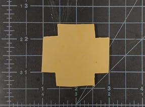
以干净的方式切割橡胶非常困难,但请尽力使线条笔直且切割成比例。这将使传感器校准更容易,读数更可靠。
接下来,我们需要将磁铁安装在底部金字塔的内部(或者任何你用来连接塔的东西)。GRF 下死点到磁铁上死点的最佳距离为 11.55 [mm],这也是最小距离。最大距离为 15.15 [mm]
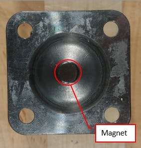
将电子设备安装到主要结构上:
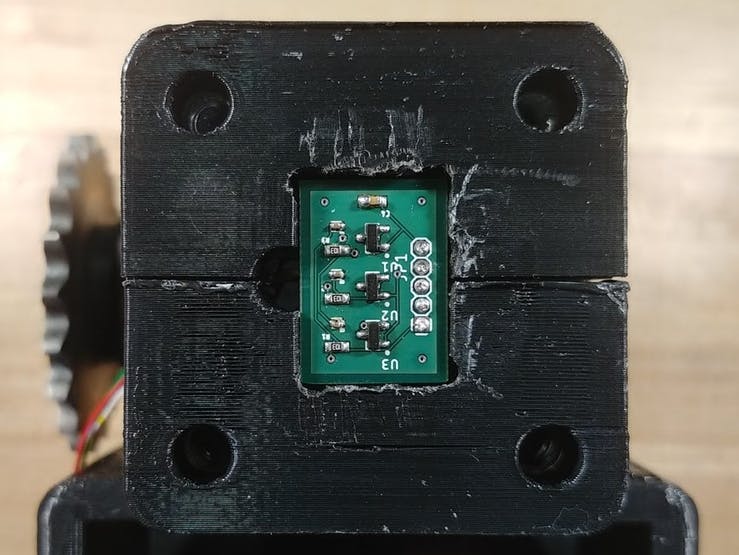
将紧急停止 (e-stop) 线穿过顶部金字塔平面的一侧,然后收集惯性测量单元 (IMU) 线,并将 e-stop 和 IMU 线向下穿过金字塔平面,穿过指示的孔并引出靠近磁铁(非链轮)侧的轴。
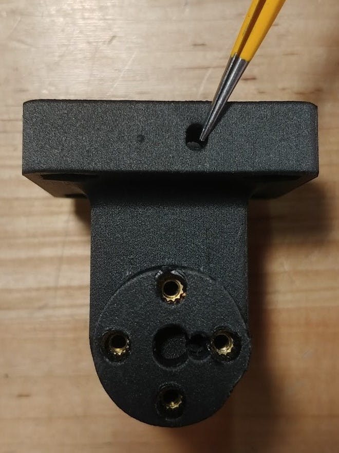
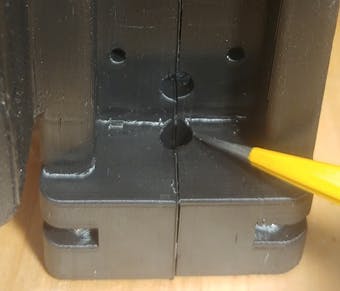
将这些和编码器线沿着外壳干净地布置到工字梁的通道,将它们固定在链条和链轮传动系统之外。
将 GRF 的电线向上穿过工字梁上的底部金字塔平面。
将主板的电源线焊接到电池组连接器端子(抹刀连接器)。
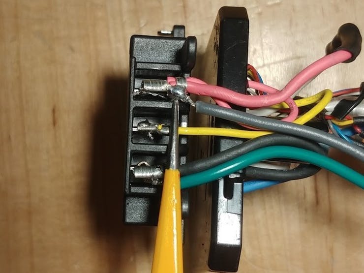
在此图像中,焊接线是绿色到黑色端子(负极)和灰色到红色端子(正极)。
如果您计划使用定制电池(没有电池监控系统)或电源运行腿,您还需要在红色(正极)和黄色(参考)端子之间焊接一个 250 [Ohm] 电阻以复制牧田电池组中热敏电阻的电阻。
注意:使用锂电池很危险,因此请遵循正确的程序并确保裸露的电线不会短路。
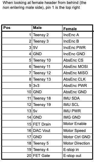
布线完所有电线后,我们需要将它们连接到主板。按照 GitHub 上文件路径“PCB->Motherboard”中的引出线描述连接 20 位和 5 位 Molex 连接器
机械组装
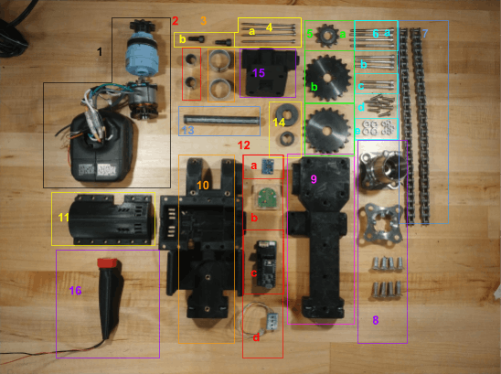
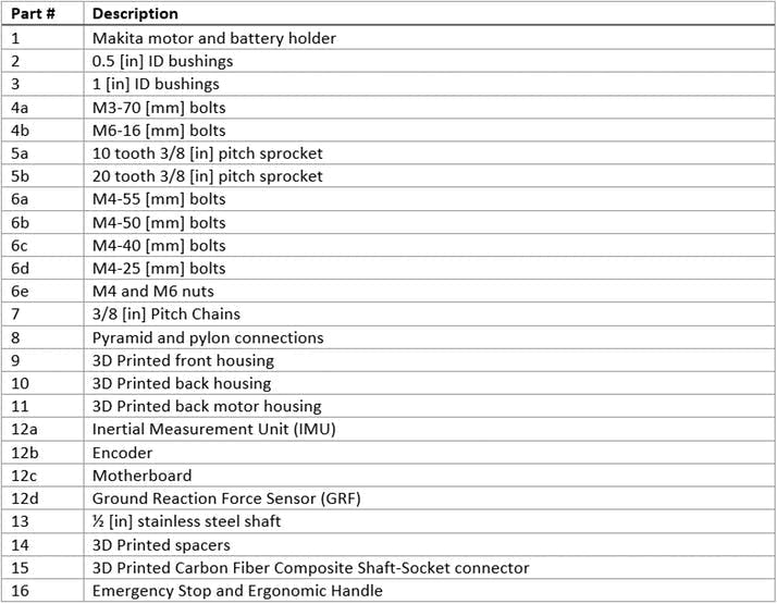
在组装支腿之前,请务必准备好下面显示和列出的所有零件。
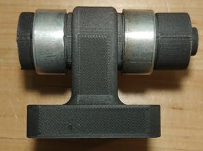
1.组装所需的第一步是修改轴套连接器衬套(第 3 部分)。如下图所示,需要使用带锯将衬套切割成 0.5 [in] 的长度,然后去毛刺。然后需要将衬套安装到轴套连接器(第 15 部分)。
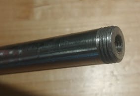
2.然后需要将 0.5 [in] 轴(第 13 部分)切割成 103 [mm],并拧上螺纹并攻丝以连接链轮。在轴两端的中心钻一个 5 [mm] 的孔,然后用 M6 螺栓攻丝。然后使用 1/2 [in]-13 模具,在轴的两个外端创建螺纹。
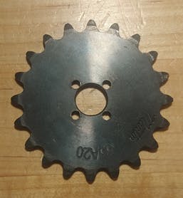
3.在轴套连接器 20 齿链轮(第 5b 部分)上,需要等距分布 4 个孔,并围绕 0.5 [in] 孔的周边钻孔。孔的直径需要为 3.4 [毫米],距链轮中心的距离为 8.89 [毫米](0.35 [英寸])(中心到中心测量值)。
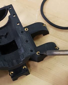
4.接下来取出所有 4 [mm] 热固插件并安装在后壳(第 10 部分)上相应的 4 [mm] 间隙孔中。对顶部轴套连接器(第 15 部分)上的 3 [mm] 热插件执行相同操作。
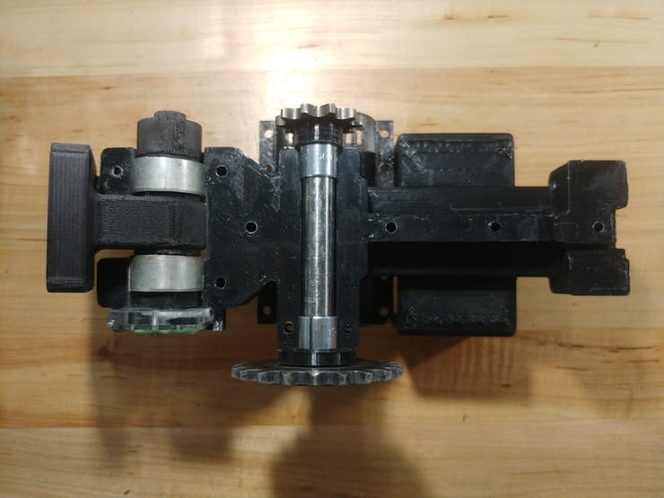
5.将两个轴连同 0.5 [in] ID 衬套和相应的垫片一起安装在框架的两半之间。将编码器(部件 12b)放入轴套连接器旁边的槽中。固定所有螺栓以将外壳的两个部分装配在一起。左侧 2 个螺栓为 M4-40 [mm](零件 6c),轴之间的 3 个螺栓为 M4-55 [mm](零件 6a),右侧三个螺栓为 M4-50 [mm](零件 6b) ,底部轴边缘的 2 个螺栓为 M4-25 [mm](第 6d 部分)。
6.使用 M3-70 [mm] 螺栓(第 4a 部分)将顶部链轮(第 5b 部分)固定到轴套接头上。
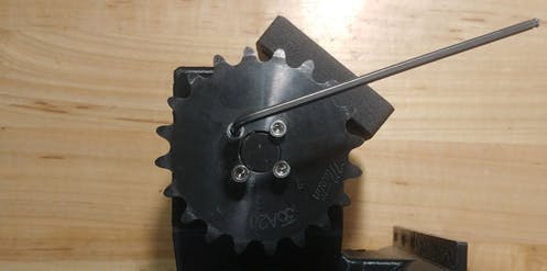
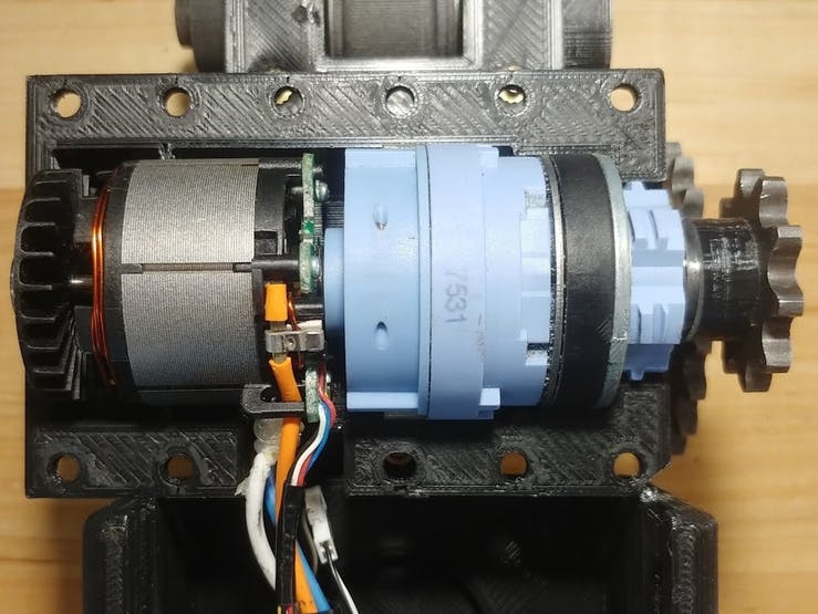
7.安装电机(第 1 部分)并拧入用于电机外壳(第 11 部分)的 M4-12 [mm] 紧固件和 M4 螺母(第 6e 部分)。
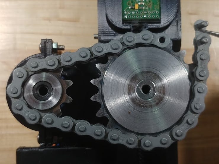
8.在两组链轮上安装链条(第 7 部分)和主链节。
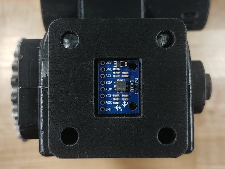
9.将 IMU(部件 12a)安装到轴套连接器上。将 GRF(第 12d 部分)放置在连接框架的底部,然后是聚氨酯橡胶,最后是金字塔(第 8 部分)以将 GRF 固定到位。
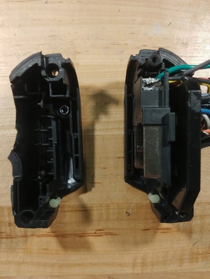
10.从电钻手柄上切下 Makit 电钻电池座,使其与顶部齐平。将电池端子(第 1 部分)和电机控制器固定在缩小的 Makita 电钻外壳中。使用 M4-12 [mm] 螺钉将钻头外壳固定到后壳上。
代码
您将需要 Arduino 和 Teensyduino(轻松)将 Teensy 4.0 上的以下代码上传到主板(第 12c 部分)。
传感器验证:
为确保所有传感器和信号线都正常工作,请将代码单独上传到 GitHub 的文件路径“Verification -> verifying[sensorName]”。每段代码都测试单个传感器及其连接。
现在一切正常,让我们开始移动这条腿。在首次启动时严格遵循这些步骤至关重要,因为不正确的传感器读数会导致系统不稳定。如果您运行了之前的所有代码并且没有返回任何错误,则传感器读数应该是正确的,但安全第一,请按照以下步骤操作:
注意:请勿在支腿通电时将 USB 数据线连接到主板,否则会损坏 Teensy。如果要在腿带电的情况下连接主板,则USB电源和板卡电源必须分开。
- 确保腿由顶部或底部金字塔固定
- 关闭紧急停止(将红色盖帽向下推)
- 使用 USB 转 micro USB 电缆将计算机连接到主板
- 上传GitHub上“Integration -> testingPcontroller”文件路径下的代码到主板
- 断开计算机与主板的连接
- 打开急停(拧红帽)
- 腿上的功率为 18 [V]
这是使腿来回摆动的代码:
/*
* Auth: Justin Francis
* Date: 11/27/19
* Ver: 1.0
* Sum: this is a position P-controller for the Open source powered prosthetic //leg,
*      it oscillates the leg back and forth between 5 deg and 85 deg from vert//ical,
*      or it can be controlled with a potentiometer remotely.
*      written for teensy 3.2
*
* Mod:
*
*/

#include
#include

//empirically determined speed curve (x = thetaDotDes [rad/s], y = command vol//tage[rad/s])
#define MOT_CONTROL_CURVE (0.67 - 0.148*log(abs(thetaDotDes)))

//teensy 3.2 limits
#define DAC_RES 1023 //10 bit
#define DAC_MAX 3.3 //[V]

//incremental encoder interrupt pins
#define IncEncA 2
#define IncEncB 3

//use this for potentiometer control
// #define POT_CTRL

//use this for plotting
// #define PLOTTING

//use this for use with battery pack, comment out if using a current limited p//ower supply
//the reason being, the battery pack can supply enough power to tear the leg a//part if a signal
//is being processed incorrectly, this keeps that from happening.
#define TRIAL

//control vars
float P = 30; //proportional gain K_u ~= 35
float k; //conversion factor for theta dot to voltage for the controller output
float motCmd; //value to output to motor controller
float err; //controller error
float thetaDes = 0; //desire joint position [rad]
float theta, thetaDotDes; //joint position [rad], desire joint velocity [rad/s]

#ifdef POT_CTRL
float inputV; //potentiometer voltage [V]
const int POT_PIN = 14; //potentiometer pin
#endif

//motor vars
const int DAC_Pin = A14; //motor speed pin
const int directionPin = 5;
const int enablePin = 4;

//incremental Encoder
Encoder inc(IncEncA,IncEncB); //interrupt attach to digital pins 2 and 3
int counts, countsOld = 0;
const float INC_RES = 4096.0; //resolution of encoder [cpr]


void setup()
{
    Serial.begin(115200); //turn on serial port (display) at 115200 baud
    //set ports
    pinMode(DAC_Pin, OUTPUT);
    pinMode(directionPin, OUTPUT);
    pinMode(enablePin, OUTPUT);

    #ifdef POT_CTRL
    pinMode(POT_PIN, INPUT);
    #endif

    //this is needed for the motor startup sequence
    digitalWrite(enablePin, LOW);
    delay(200);

    #ifdef PLOTTING
    Serial.println("theta thetaDes");
    #endif
}


/*
* function to control the motor, takes in a desired velocity and commands the motor
* no return
*/
void MotorDrive(float thetaDotDes)
{
    if(thetaDotDes >= 0.0)
    {
    digitalWrite(directionPin, HIGH);
    }
    else
    {
    digitalWrite(directionPin, LOW);
    }
    digitalWrite(enablePin, HIGH);
    motCmd = MOT_CONTROL_CURVE; //[V]
    motCmd = constrain(motCmd, 0.0, .75); //anything outside of this voltage r            //ange cause the controller to pause
    analogWrite(DAC_Pin, (int)(motCmd*DAC_RES/DAC_MAX)); //convert command int        //o voltage
}


float i = 0; //used for oscillations
void loop()
{
    //read sensor
    counts = inc.read();

    //potentiometer control
    #ifdef POT_CTRL
    inputV = analogRead(POT_PIN) * (3.3/1024); //[V]
    #endif

    //standard oscillations
    #ifndef POT_CTRL
    thetaDes = (PI/2.2*sin(i));
    i += 0.0001; //this needs to decrease if the teensy 4.0 is used because of    //faster clock
    #endif

    //convert to radians
    theta = (((float)counts/INC_RES))*2*PI; //[rad]

    #ifdef POT_CTRL
    thetaDes = inputV * (PI/(3.3*2)) - .5; //[rad]
    #endif

    #ifdef TRIAL
    thetaDes  = constrain(thetaDes, -.5, 1.5);
    #endif

    #ifdef PLOTTING
    Serial.print(theta*.25);Serial.print("\t");Serial.println(thetaDes*.25);
    #endif

    //find err
    err = thetaDes - theta; //rad

    //calc correction
    thetaDotDes = P * err; //[rad/s]

    //command system
    MotorDrive(thetaDotDes);

    //feedback (not needed for P controller)
}
现在腿应该来回摆动,在摆动的两端停几秒钟。
第一次试运行后,可以使用以下步骤为腿加电。
- 打开急停(拧红帽)
- 以 18 [V] 为腿供电
可选的无线通信(高级)
通过使用第二个 Raspberry Pi Zero W 作为控制器,可以最轻松地进行无线通信。然后可以通过连接到现有网络或将其中一个树莓派设置为接入点来实现设备之间的通信。
连接到同一网络后,Python 的套接字库可用于使用 GitHub 上文件路径“wireless_communication”中的代码在两个 Pi 之间创建服务器(在腿上)客户端(远程)关系。
服务器设置(Python):
import socket

# establish connection
HOST = "INSERT SERVER IP ADDRESS"
PORT = "INSERT OPEN PORT" # e.g. port above 5000
s = socket.socket(socket.AF_INET, socket.SOCK_STREAM)
print "socket created"

# check for valid host and port
try:
    s.bind((HOST,PORT))
except socket.error:
    print "bind Failed"

# establish connection
s.listen(1)
print "Socket awaiting messages"
(conn, addr) = s.accept()
print "connected"

# await and receive messages
while True:
    data = conn.recv(1024)
    print data

# close connection when finished
    conn.close()
客户端设置(Python):
import socket
import Adafruit_ADS1x15
import time

# Configure wireless connection with server (board on leg)
HOST = "INSERT SERVER IP ADDRESS"
PORT = "INSERT OPEN PORT" # e.g. port above 5000

# Connect to server host/port
s = socket.socket(socket.AF_INET, socket.SOCK_STREAM)
s.connect((HOST, PORT))

# ADC Converter: Create an ADS1115 ADC (16-bit) instance.
adc = Adafruit_ADS1x15.ADS1115()

# Choose Gain
GAIN = 1

while True:
    # Read all the ADC channel values in a list.
    # Our joystick has two channels         (direction and button)
    values = [0]*2
    for i in range(2):
        # Read the specified ADC channel using the previously set gain value.
        values[i] = adc.read_adc(i, gain=GAIN)

        # we are currently only interested in the direction value
        command = str(values[0])

        # send command to the server
        s.send(command)

        # delay
        time.sleep(0.5)
通过模数转换器 ( ADC),控制器的 Pi 可以读取操纵杆的 ADC 通道值,然后将其发送到腿的 Pi。最后,通过 pySerial 库,腿部的 Pi 可以将这些模拟值传输到 Teensy 4.0,以控制电机的速度和方向。
将代码添加到服务器代码的顶部(Python):
import serial
import time

# connect with teensy, choose baud rate
ser = serial.Serial('/dev/tty/ACM0', 9600)

time.sleep(.5)
将代码添加到服务器底部while 循环以与 Teensy (Python)通信:
# send command to teensy
    ser.write(str(data))
    time.sleep(.1)
青少年设置(C++):
void setup() {
    Serial1.begin(9600);
    Serial.begin(9600);
}

void loop() {
    String readString = "";

    // read in message
    while (Serial.available())
    {
        delay(30);
        if (Serial.available() > 0)
        {
            char c = Serial.read();
            readString += c;
        }
    }

    // print message to serial monitor or use value to control motor
    if (readString.length() > 0)
    {
        Serial.println(readString);
    }
}
我们使用无线通信让控制、数据收集、代码重构和调试更加高效和方便。
声明:本文内容及配图由入驻作者撰写或者入驻合作网站授权转载。文章观点仅代表作者本人,不代表电子发烧友网立场。文章及其配图仅供工程师学习之用,如有内容侵权或者其他违规问题,请联系本站处理。 举报投诉
- 相关下载
- 相关文章


