
资料下载


Spresense GPS摄像头开源分享
吴湛
分享资料个
ESP32 还将与 1.8 英寸 TFT 显示屏连接。
相机子系统
为了实现 ESP32 摄像头,使用了 OV7670 摄像头模块。OV7670 配置为在 QCIF 分辨率模式下运行。这是 VGA 模式下的按比例缩小的分辨率。解码后的相机数据然后通过 ST7735 控制器直接传输到 1.8 英寸 TFT 显示器。相机使用与 OneWire (i2C) 非常相似的 SCCB 协议通过两个引脚进行配置。
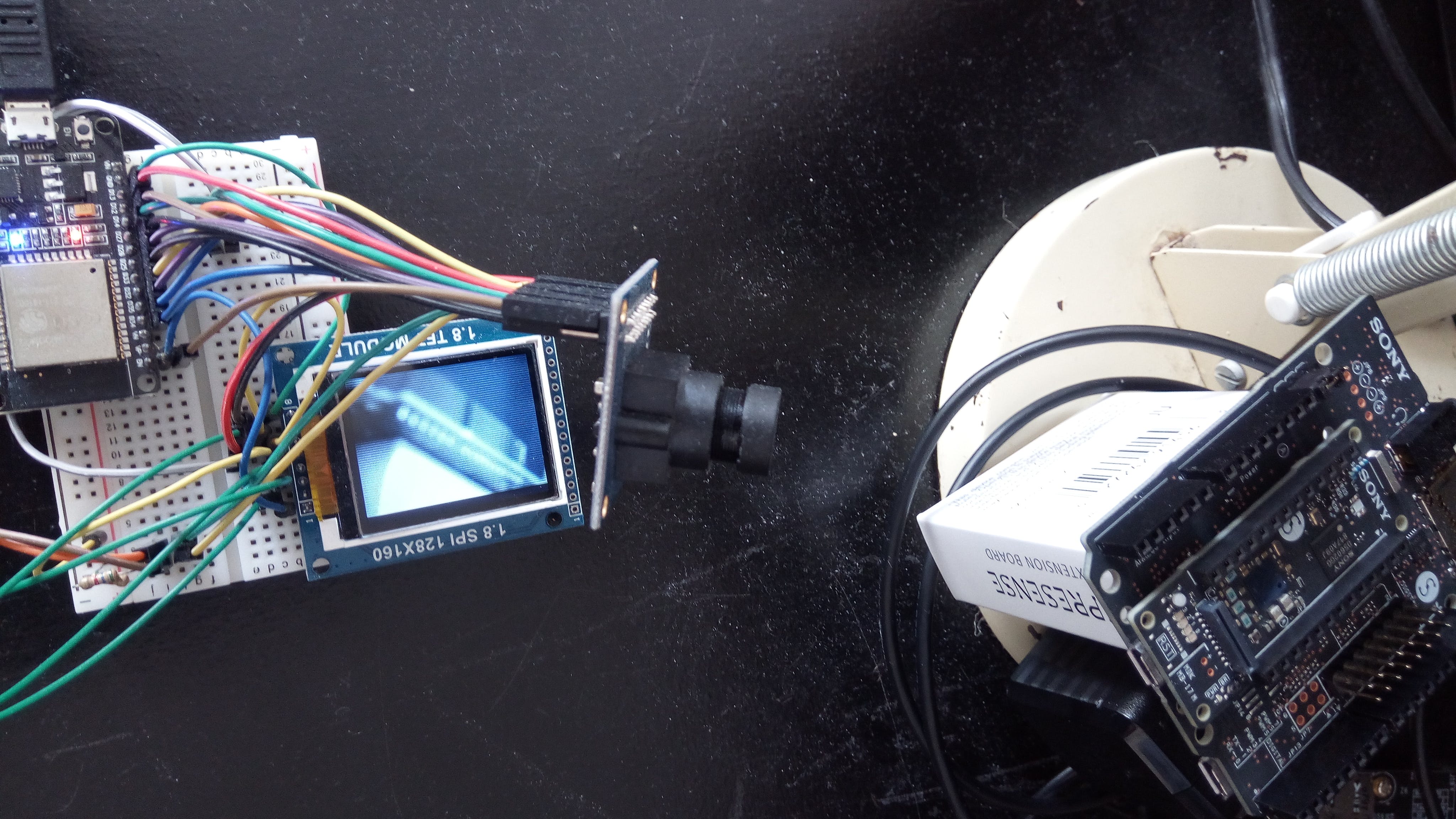
TFT 连接到 SPI 总线。上述测试验证了摄像头和 TFT 显示屏的正常工作。
下一步是测试 WiFi 功能。
要在第一行对此进行测试,请输入您的 WiFi 网络名称和密码。
#define ssid1        "YOUR_WIFI_SSID"
#define password1    "YOUR_PASSWORD"
取消注释这些行:
 //camera->oneFrame();
 //serve();
 //displayRGB565(camera->frame, camera->xres, camera->yres);
现在打开浏览器并输入摄像机的 IP。
下一步是再次修改代码以在设置标志时启用 WiFi 传输。
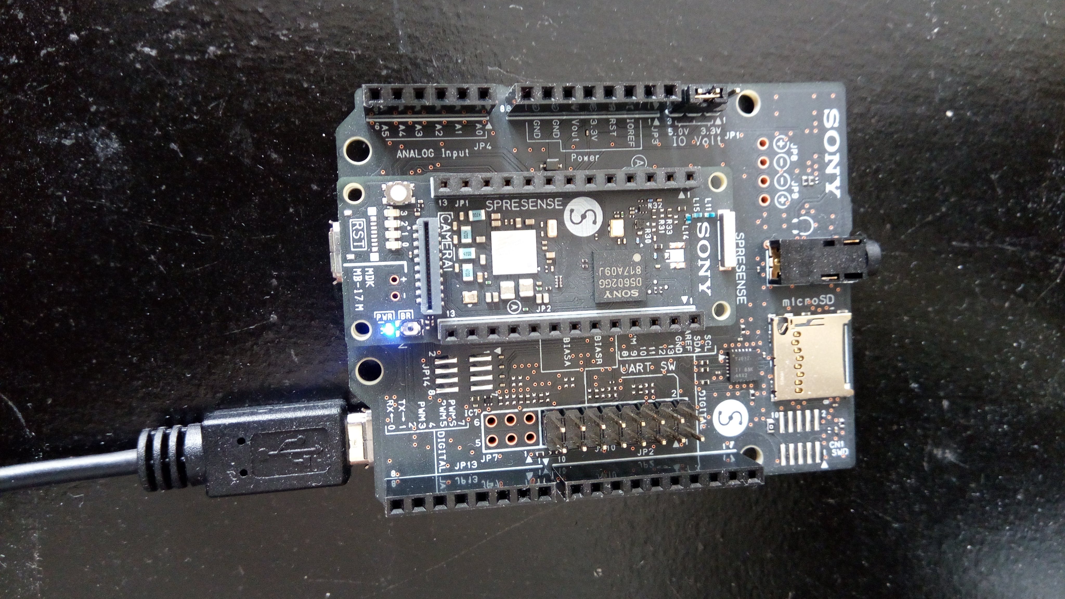
GPS子系统
该系统使用 Spresense GPS 示例应用程序。具体来说,我正在使用 GNSS 跟踪器。这需要将 SD 卡与基板结合使用。
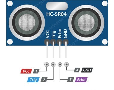
超声波传感器
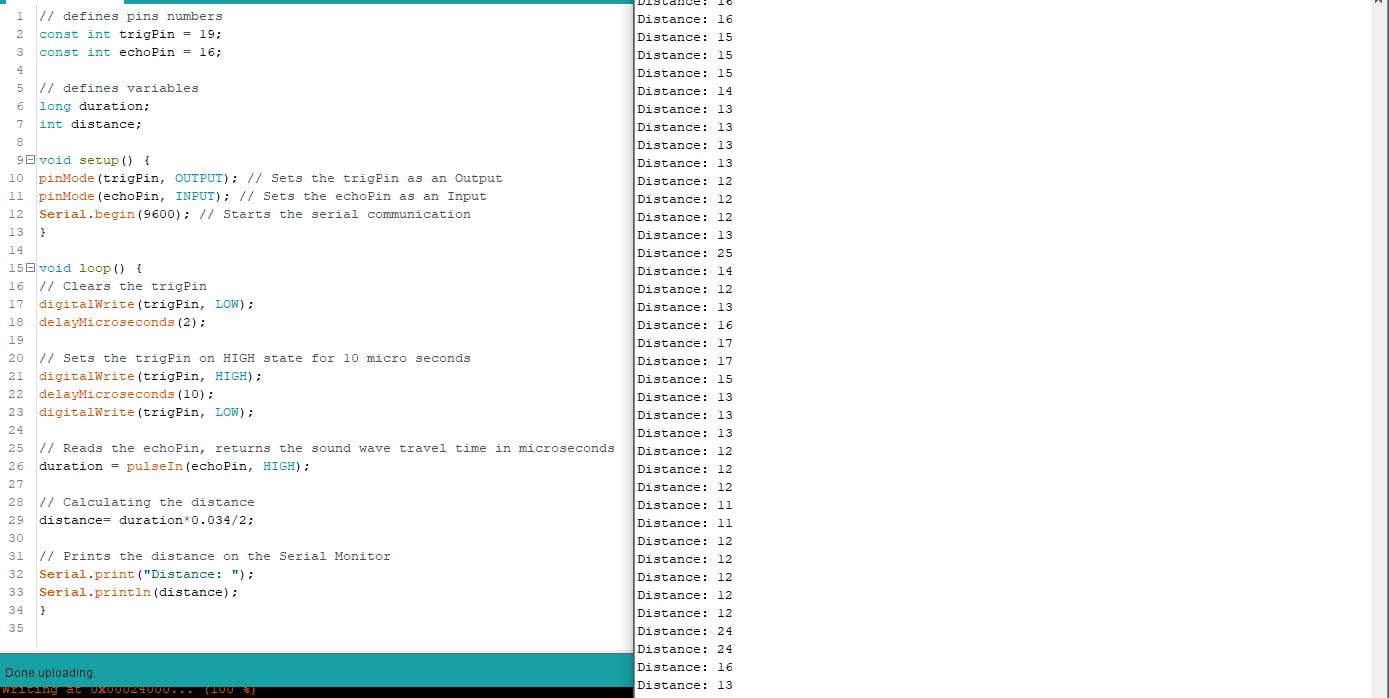
HCSR-04 用作距离传感器。这是一种超声波传感器,通过测量接收到的回波的长度来测量距离。
下面的代码用于测试操作:
// defines pins numbers
const int trigPin = 2;
const int echoPin = 5;
// defines variables
long duration;
int distance;
void setup() {
pinMode(trigPin, OUTPUT); // Sets the trigPin as an Output
pinMode(echoPin, INPUT); // Sets the echoPin as an Input
Serial.begin(9600); // Starts the serial communication
}
void loop() {
// Clears the trigPin
digitalWrite(trigPin, LOW);
delayMicroseconds(2);
// Sets the trigPin on HIGH state for 10 micro seconds
digitalWrite(trigPin, HIGH);
delayMicroseconds(10);
digitalWrite(trigPin, LOW);
// Reads the echoPin, returns the sound wave travel time in microseconds
duration = pulseIn(echoPin, HIGH);
// Calculating the distance
distance= duration*0.034/2;
// Prints the distance on the Serial Monitor
Serial.print("Distance: ");
Serial.println(distance);
}
扩张的想法
添加语音交互。关键字识别和音频反馈。
使用 LST 网络从加速度计数据中添加 AI 功能。这是一个进展中的工作。
声明:本文内容及配图由入驻作者撰写或者入驻合作网站授权转载。文章观点仅代表作者本人,不代表电子发烧友网立场。文章及其配图仅供工程师学习之用,如有内容侵权或者其他违规问题,请联系本站处理。 举报投诉
- 相关下载
- 相关文章


