
资料下载


使用RMS到直流转换器的仪器电路
分享资料个
INTRODUCTION
It is widely acknowledged that RMS (Root of the Mean of the Square) measurement of waveforms furnishes the most accurate amplitude information.1 Rectify-andaverage schemes, usually calibrated to a sine wave, are only accurate for one waveshape. Departures from this waveshape result in pronounced errors. Although accurate, RMS conversion often entails limited bandwidth, restricted range, complexity and diffi cult to characterize dynamic and static errors. Recent developments address these issues while simultaneously improving accuracy. Figure 1 shows the LTC®1966/LTC1967/LTC1968 device family. Low frequency accuracy, including linearity and gain error, is inside 0.5% with 1% error at bandwidths extending to 500kHz. These converters employ a sigma-delta based computational scheme to achieve their performance.
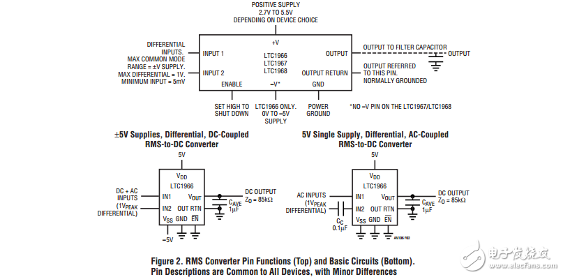
Figure 2’s pinout descriptions and basic circuits reveal an easily applied device. An output fi lter capacitor is all that is required to form a functional RMS-to-DC converter. Split and single supply powered variants are shown. Such ease of implementation invites a broad range of application; examples begin with Figure 3.
Isolated Power Line Monitor
BEFORE PROCEEDING ANY FURTHER, THE READER IS WARNED THAT CAUTION MUST BE USED IN THE CONSTRUCTION, TESTING AND USE OF THIS CIRCUIT. HIGH VOLTAGE, LETHAL POTENTIALS ARE PRESENT IN THIS CIRCUIT. EXTREME CAUTION MUST BE USED IN WORKING WITH, AND MAKING CONNECTIONS TO, THIS CIRCUIT. REPEAT: THIS CIRCUIT CONTAINS DANGEROUS, HIGH VOLTAGE POTENTIALS. USE CAUTION.
声明:本文内容及配图由入驻作者撰写或者入驻合作网站授权转载。文章观点仅代表作者本人,不代表电子发烧友网立场。文章及其配图仅供工程师学习之用,如有内容侵权或者其他违规问题,请联系本站处理。 举报投诉
- 相关下载
- 相关文章


