
资料下载


智能传感器在4至20毫安控制回路
分享资料个
智能传感器在4至20毫安控制回路
本文着眼于将传感器集成到工业自动化应用中的4到20 mA控制回路和现场总线实现中。将智能添加到传感器允许更多的控制和选项的封闭或开放的控制回路与更紧的延迟,本文着眼于不同的方法来实现一个智能传感器控制回路。看起来那是控制回路如德克萨斯仪器xtr117收发器和Avago公司的hcpl-4200光耦优化设备,以及控制器,对这些控制回路,如从模拟设备的aduc816传感器优化。
许多传感器是专门为工业过程控制系统中常见的4到20 mA控制回路而设计的。
一个数字到模拟转换器(DAC)和一个优化控制器的结合,加上清晰定义的4到20 mA范围,提供了一个成本效益和可靠的传感器网络。使用一个非零输出电流(4毫安)的零点有两个关键优势。它允许在发射机上开路检测,如果电流要求小于4毫安,则向传感器提供功率。通过仔细的系统设计,这使得传感器和数据采集设备可以直接由网络供电,可以大大简化工业自动化设备的发展。
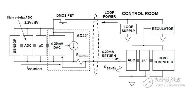
Figure 1 shows a 4 to 20 mA output smart sensor that is completely powered by the loop power supply. In order for this to work, the sum total of all the circuits under loop power can be no more than 4 mA. The heart of the circuit is the AD421 loop-powered 16-bit DAC from Analog Devices. The internal 4 to 20 mA DAC current, as well as the rest of the return current from the AD421 and the other circuits under loop power, flows through the RSENSE resistor. The sensing circuit compensates for the additional return current and ensures that the actual loop return current corresponds to that required by the digital code applied to the DAC through the microcontroller. The sensor output is digitized by a sigma-delta ADC.
声明:本文内容及配图由入驻作者撰写或者入驻合作网站授权转载。文章观点仅代表作者本人,不代表电子发烧友网立场。文章及其配图仅供工程师学习之用,如有内容侵权或者其他违规问题,请联系本站处理。 举报投诉
-
 wangzguo
2020-09-29
0 回复 举报谢谢 收起回复
wangzguo
2020-09-29
0 回复 举报谢谢 收起回复
- 相关下载
- 相关文章


