
资料下载

ILI9341显示和LOLIN D32载板开源
描述
ILI9341 显示和 LOLIN D32 载板
问候。
所以这就是载板,它基本上是一个连接板,用于连接 ILI9341 显示器和 Wemos Lolin D32 Pro 板。
准备这个项目的目标是在不使用电线和面包板的情况下将显示器与 ESP32 板连接起来,以准备与显示器相关的项目。
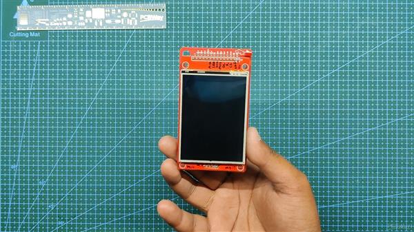
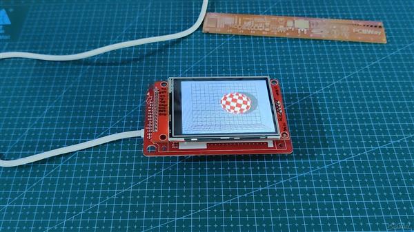
该板可替代我们为将显示器与 ESP32 板连接所做的面包板设置。
本文包含载板的构建过程以及使用 tft_eSPI 库的 ESP32 和 ILI9341 显示实现。
让我们开始吧!
所需材料
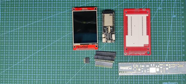
以下是此内置所需的东西-
- ILI9341 显示器
- Wemos 洛林 D32 Pro
- 定制 PCB(由 PCBWAY 提供)
- 用于显示器和 ESP32 板的母头针连接器
关于ili9341显示器
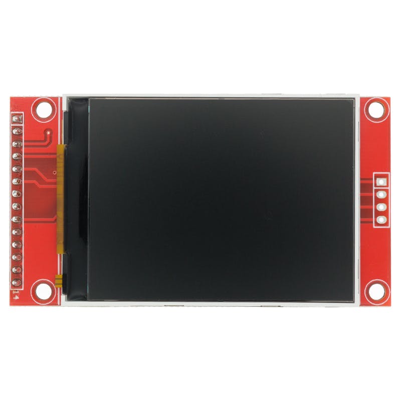
ILI9341 是一款 262,144 色单芯片 SOC 驱动器,用于分辨率为 320x240 像素的 TFT 液晶显示器。
ILI9341 可在 1.65V ~ 3.3VI/O 接口电压下工作,并集成电压跟随器电路以产生驱动 LCD 的电压电平。
这个项目中使用的显示模块有一个内置的触摸界面,里面有一个 SD 卡读卡器插槽,我们可以用它来读取 SD 卡数据。
以下是ILI9341 Pinout-
- PIN1- VCC
- PIN2-地
- PIN3-CS
- PIN4-复位
- PIN5-直流
- PIN6-MOSI(液晶屏)
- PIN7-SCK(液晶屏)
- PIN8-LED
- PIN9-味噌 (LCD)
- PIN10- T_CLK
- PIN11- T_CS
- PIN12- T_DIN
- PIN13- T_D0
- PIN14-T_IRQ
使用 ESP32 Lolin D32 Pro
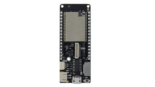
Wemos Lolin D32 Pro 用于驱动该项目中的显示器。
它基于具有 16MB/4MB FLASH、4MB PSRAM 的 ESP32-WROVER 模块,并具有板载 SD 卡读卡器、显示端口和 I2C 连接器。
接线连接
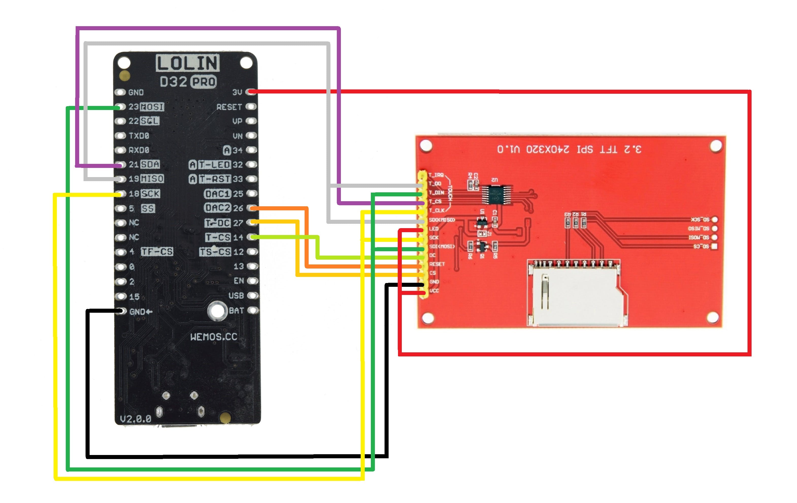
至于 ESP32 Board 和 ILI9341 Display 之间的基本接线,我们按照接线图将它们连接起来。
- 显示器的VCC到3.3V
- 地到地
- CS (LCD) 至 D27
- 重置为 D26
- 直流到 D14
- MOSI转D23
- SCK 到 D18
- LED 至 3.3V(用于背光)
- 味噌到 D19
- 触摸 CLK 到 D18 (SCK)
- 触摸 CS 到 D21
- 触摸 DIN 到 D23 (MOSI)
- 触摸 DO 到 D19 (MISO)
电路板设计
为了准备载板,我们使用布线连接并准备一个简单的原理图,将所有引脚断开并添加用于将显示器与 ESP32 连接的接头引脚。
此外,还有一个 CON2 用于添加用于为该设置供电的外部电池以及与 ESP32 的 D2 连接的 LED。
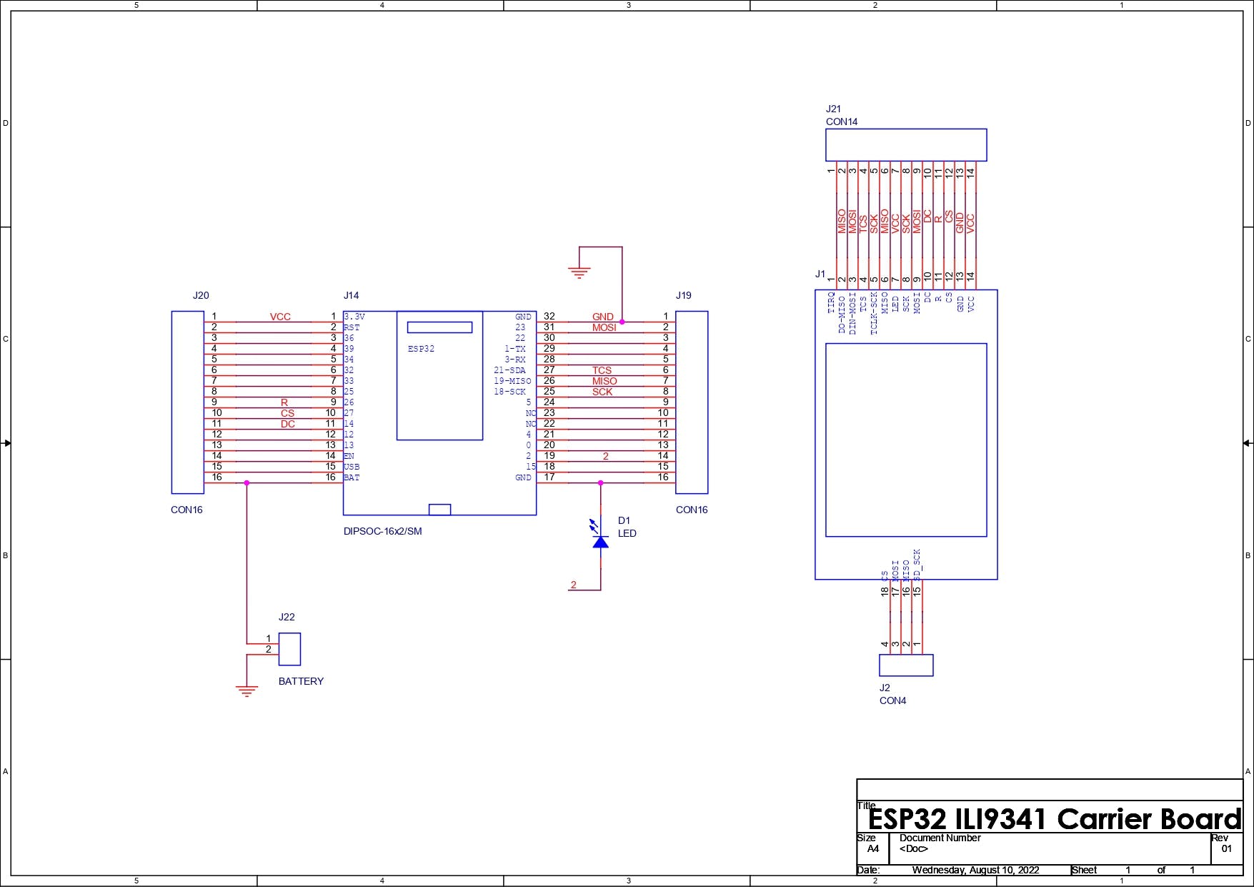
完成原理图文件后,我们将其转换为电路板文件并准备 96mm x 55mm 外形尺寸的 PCB。
ILI9341 显示器添加在顶部,ESP32 位于底部,我们在显示端口和 ESP32 连接附近添加了额外的连接器,因此我们可以将接头引脚添加到这些连接器以使用 ESP32 GPIO 引脚或使用显示引脚。
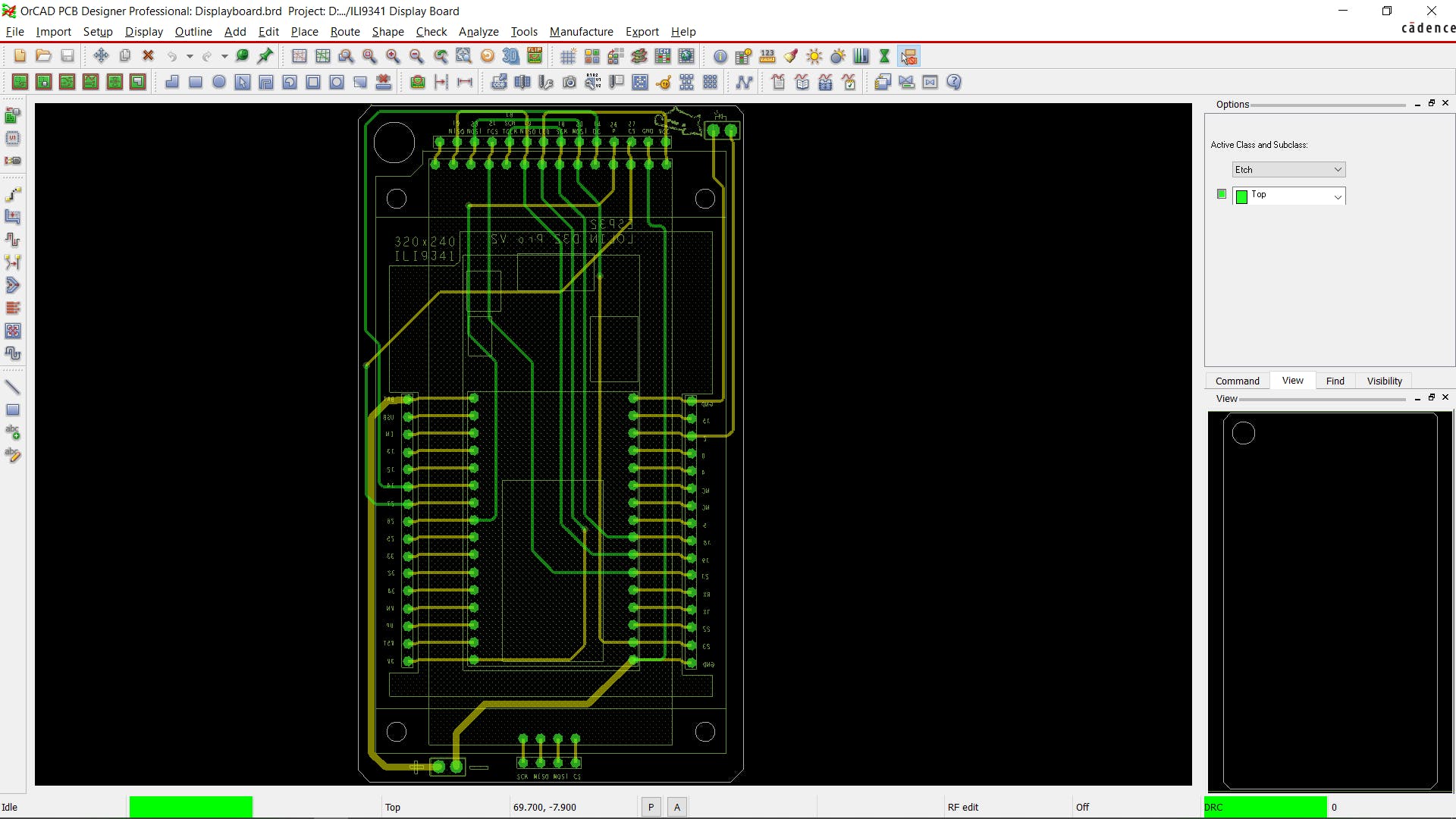
最终确定电路板后,我们最后一次检查它,然后导出其 Gerber 数据,以便我们将其发送给 PCB 制造商以获取样品。
PCBWAY
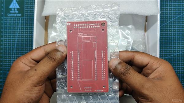
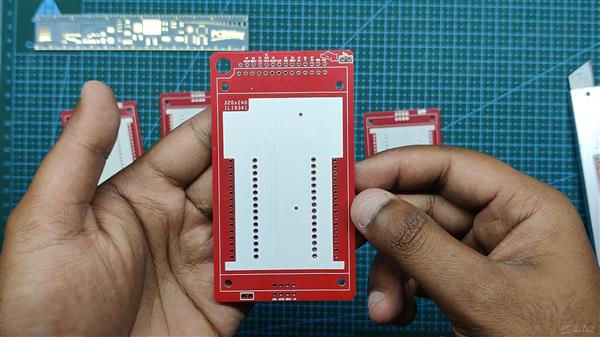
完成PCB设计并导出Gerber数据后,我们将其上传到PCBWAY的报价页面下订单。
RED Soldermask 正在用于这个项目,因为我们在过去的项目中已经使用了 RED PCB,它看起来很漂亮,而且显示器有 RED PCB,所以使用 RED Soldermask 似乎是正确的。
PCB 在一周内交付,速度非常快。
至于PCB的质量,每块PCB都制作正确,没有任何错误或印刷错误。
整体质量非常好,如果您需要以更低的成本获得优质的 PCB 服务,我建议你们检查一下。
接下来,我们准备电路板组装过程。
板组装
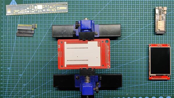
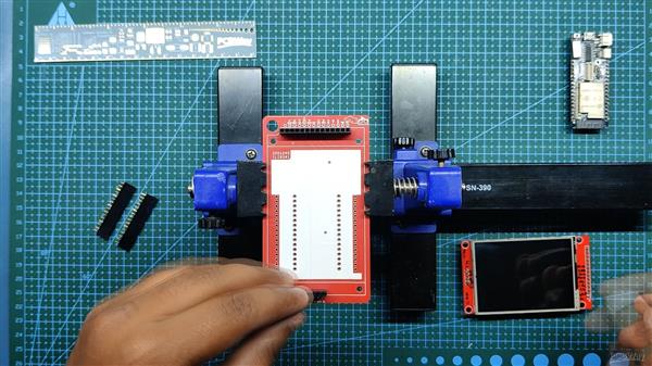
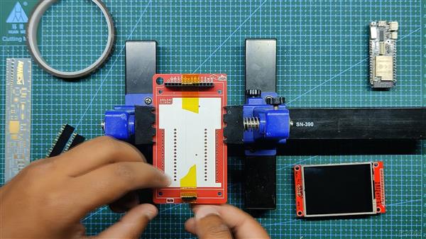
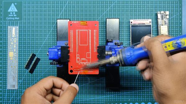
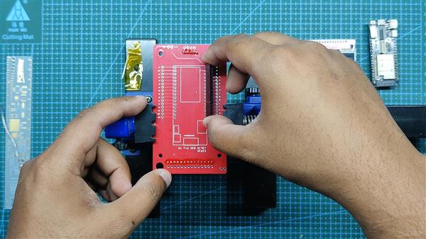
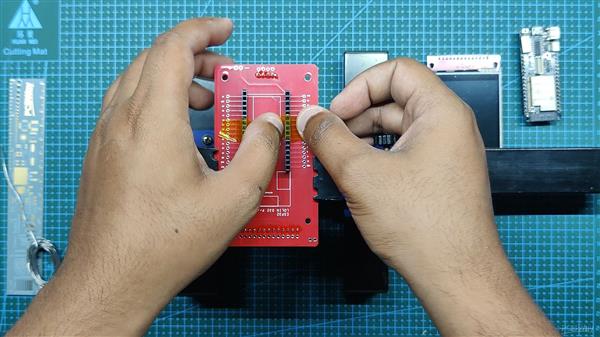
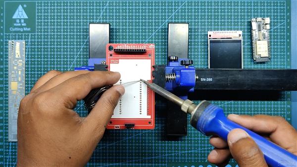
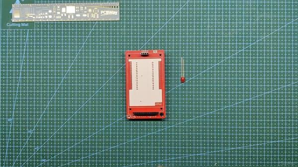
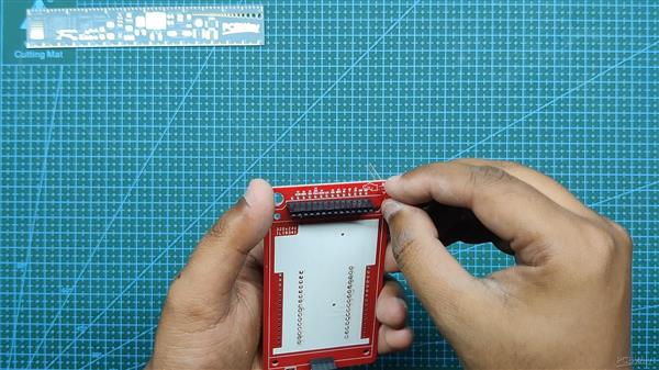
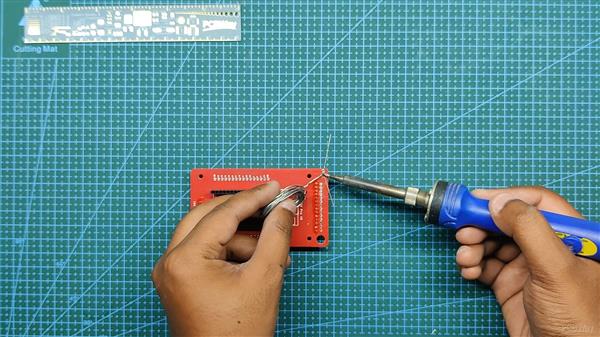
我们首先收集组装过程所需的所有组件,包括用于 ESP32 和 LCD 屏幕的接头引脚以及用于焊接过程的定制 PCB 和 PCB 固定夹具。
- 我们首先将 PCB 添加到 PCB 焊接夹具中。
- 接下来,我们在 PCB 的顶部添加用于显示器的接头引脚,我们添加 Kapton 胶带以在焊接时将接头引脚保持在原位。(Kapton Tape 是一种用于电子产品的热阻胶带,也称为金胶带,用于电池或电芯)
- 我们从底部焊接连接器。
- 在此之后,我们重做上述过程以添加 ESP32 的插头引脚,方法是将引脚放置在它们的焊盘中,并在焊接过程中使用 Kapton 胶带固定连接器。
- 然后,我们在 LED 连接垫上以正确的极性焊接一个扁平的 3V LED。
- 董事会现已完成
结果到目前为止。
这是董事会的外观。
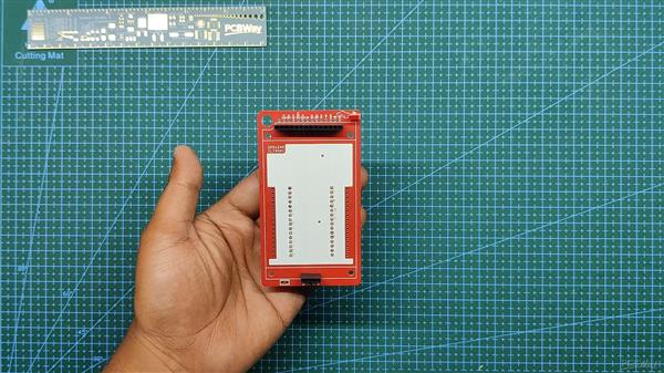
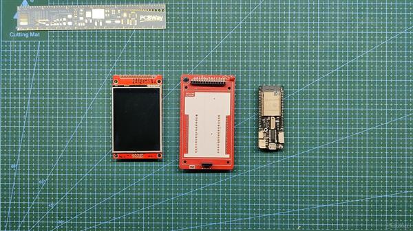
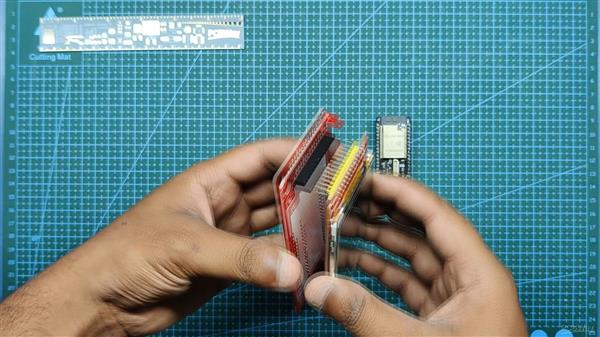
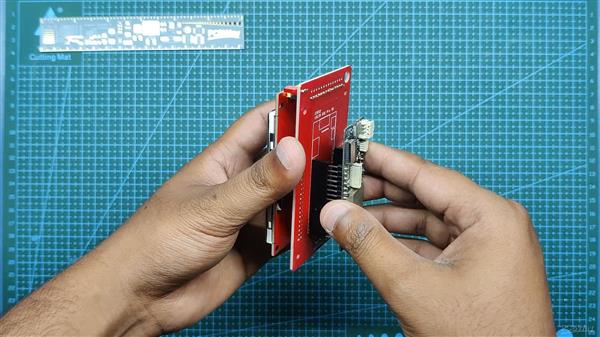
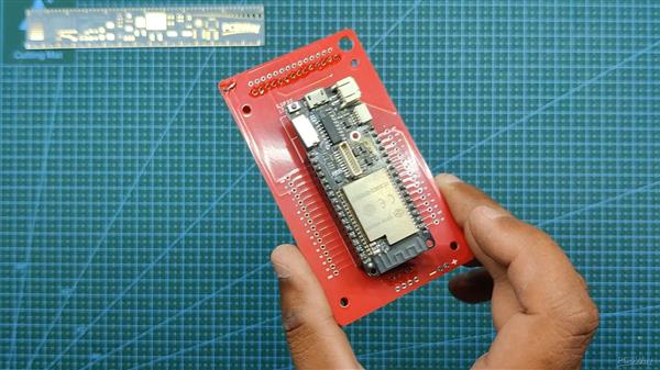
我们现在将 ESP32 和 Display 添加到载板上并准备该项目的软件部分。
库 TFT_eSPI
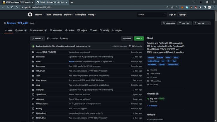
为了驱动 ILI9341 显示器,我们使用 Bodmer 流行的 TFT_eSPI 库。
https://github.com/Bodmer/TFT_eSPI
TFT_eSPI 是一个了不起的库,支持所有使用的主要显示器,如 ILI9430、ST7735,甚至圆形 LCD GC9A01。
如果有兴趣,请查看我之前关于 GC9A01 显示器的项目,两者都很相似。
https://www.hackster.io/Arnov_Sharma_makes/esp32-and-round-oled-smart-watch-concept-3a5601
- 我们首先去它的 Github Page 并下载 RAW 文件。
- 接下来,我们在 Documents>Arduino>Libraries 中提取文件夹,我们将在其中保存所有自定义库。
- 我们打开 Arduino IDE 并看到库管理器中添加的 TFT_eSPI。
为了使用不同类型的显示器,我们在这个库的 User_Setup 文件中进行了更改,默认设置为 ILI9341 显示器,因此我们无需更改任何内容以使用当前显示器,但如果我们想使用不同的显示器,如 GC9A01 圆形LCD,然后我们必须编辑 User_Setup.h 文件。
注意 - 如果您是第一次使用 ESP32,Arduino IDE 默认不包含 ESP32 板,您必须通过将以下链接放入 Arduino IDE 的首选项中添加它们,然后通过板管理器添加它们。
https://dl.espressif.com/dl/package_esp32_index.json
示例草图
为了测试设置,我们首先通过 USB 电缆将 ESP32 开发板与 Arduino IDE 连接,然后将开发板更改为 Lolin D32 Pro 并选择正确的端口。
我们转到 文件>示例> TFT_eSPI>320x240 并选择任何草图将其上传到 ESP32。
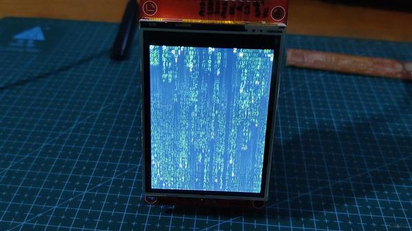
矩阵
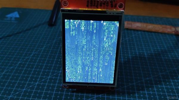
我们首先选择 TFT_Matrix Sketch,它显示随机数字和字母从显示屏的顶部滚动到底部,就像在电影矩阵中一样。
这是草图-
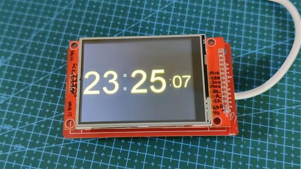
数码时钟
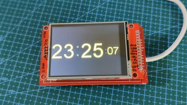
接下来,我们使用 Digital_Clock Sketch 来显示 MCU 在上传之前从计算机获取的实时数据。
如果我们重置或拔下设备并从外部源重新启动它,时间将重置。
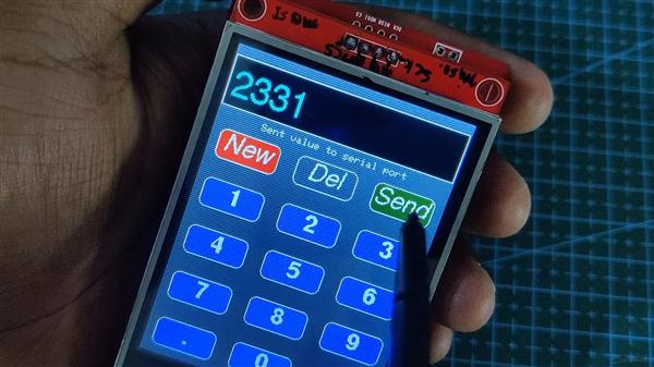
键盘 240x320
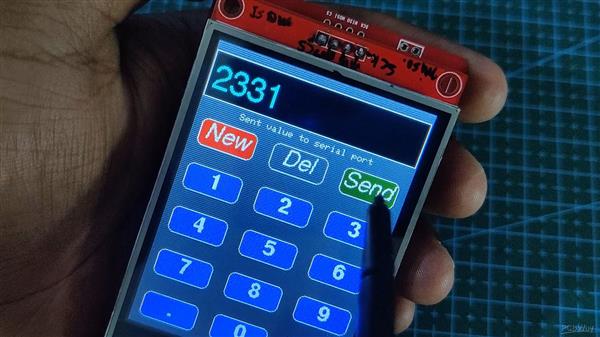
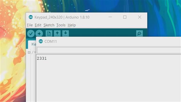
这是一个有趣的草图,一个交互式数字键盘草图,我们可以在上面输入任何数字,并将该数字发送到串行监视器。
此 Sketch 利用 LCD 显示器的触控功能。
// The SPIFFS (FLASH filing system) is used to hold touch screen // calibration data #include "FS.h" #include #include // Hardware-specific library TFT_eSPI tft = TFT_eSPI(); // Invoke custom library // This is the file name used to store the calibration data // You can change this to create new calibration files. // The SPIFFS file name must start with "/". #define CALIBRATION_FILE "/TouchCalData1" // Set REPEAT_CAL to true instead of false to run calibration // again, otherwise it will only be done once. // Repeat calibration if you change the screen rotation. #define REPEAT_CAL false // Keypad start position, key sizes and spacing #define KEY_X 40 // Centre of key #define KEY_Y 96 #define KEY_W 62 // Width and height #define KEY_H 30 #define KEY_SPACING_X 18 // X and Y gap #define KEY_SPACING_Y 20 #define KEY_TEXTSIZE 1 // Font size multiplier // Using two fonts since numbers are nice when bold #define LABEL1_FONT &FreeSansOblique12pt7b // Key label font 1 #define LABEL2_FONT &FreeSansBold12pt7b // Key label font 2 // Numeric display box size and location #define DISP_X 1 #define DISP_Y 10 #define DISP_W 238 #define DISP_H 50 #define DISP_TSIZE 3 #define DISP_TCOLOR TFT_CYAN // Number length, buffer for storing it and character index #define NUM_LEN 12 char numberBuffer[NUM_LEN + 1] = ""; uint8_t numberIndex = 0; // We have a status line for messages #define STATUS_X 120 // Centred on this #define STATUS_Y 65 // Create 15 keys for the keypad char keyLabel[15][5] = {"New", "Del", "Send", "1", "2", "3", "4", "5", "6", "7", "8", "9", ".", "0", "#" }; uint16_t keyColor[15] = {TFT_RED, TFT_DARKGREY, TFT_DARKGREEN, TFT_BLUE, TFT_BLUE, TFT_BLUE, TFT_BLUE, TFT_BLUE, TFT_BLUE, TFT_BLUE, TFT_BLUE, TFT_BLUE, TFT_BLUE, TFT_BLUE, TFT_BLUE }; // Invoke the TFT_eSPI button class and create all the button objects TFT_eSPI_Button key[15]; //------------------------------------------------------------------------------------------ void setup() { // Use serial port Serial.begin(9600); // Initialise the TFT screen tft.init(); // Set the rotation before we calibrate tft.setRotation(0); // Calibrate the touch screen and retrieve the scaling factors touch_calibrate(); // Clear the screen tft.fillScreen(TFT_BLACK); // Draw keypad background tft.fillRect(0, 0, 240, 320, TFT_DARKGREY); // Draw number display area and frame tft.fillRect(DISP_X, DISP_Y, DISP_W, DISP_H, TFT_BLACK); tft.drawRect(DISP_X, DISP_Y, DISP_W, DISP_H, TFT_WHITE); // Draw keypad drawKeypad(); } //------------------------------------------------------------------------------------------ void loop(void) { uint16_t t_x = 0, t_y = 0; // To store the touch coordinates // Pressed will be set true is there is a valid touch on the screen boolean pressed = tft.getTouch(&t_x, &t_y); // / Check if any key coordinate boxes contain the touch coordinatesfor (uint8_t b = 0; b < 15; b++) { if (pressed && key[b].contains(t_x, t_y)) { key[b].press(true); // tell the button it is pressed } else { key[b].press(false); // tell the button it is NOT pressed } } // Check if any key has changed statefor (uint8_t b = 0; b < 15; b++) { if (b < 3) tft.setFreeFont(LABEL1_FONT); else tft.setFreeFont(LABEL2_FONT); if (key[b].justReleased()) key[b].drawButton(); // draw normal if (key[b].justPressed()) { key[b].drawButton(true); // draw invert // if a numberpad button, append the relevant # to the numberBufferif (b >= 3) { if (numberIndex < NUM_LEN) { numberBuffer[numberIndex] = keyLabel[b][0]; numberIndex++; numberBuffer[numberIndex] = 0; // zero terminate } status(""); // Clear the old status } // Del button, so delete last charif (b == 1) { numberBuffer[numberIndex] = 0; if (numberIndex > 0) { numberIndex--; numberBuffer[numberIndex] = 0;//' '; } status(""); // Clear the old status } if (b == 2) { status("Sent value to serial port"); Serial.println(numberBuffer); } // we dont really check that the text field makes sense// just try to callif (b == 0) { status("Value cleared"); numberIndex = 0; // Reset index to 0 numberBuffer[numberIndex] = 0; // Place null in buffer } // Update the number display field tft.setTextDatum(TL_DATUM); // Use top left corner as text coord datum tft.setFreeFont(&FreeSans18pt7b); // Choose a nicefont that fits box tft.setTextColor(DISP_TCOLOR); // Set the font colour // Draw the string, the value returned is the width in pixelsint xwidth = tft.drawString(numberBuffer, DISP_X + 4, DISP_Y + 12); // Now cover up the rest of the line up by drawing a black rectangle. No flicker this way// but it will not work with italic or oblique fonts due to character overlap. tft.fillRect(DISP_X + 4 + xwidth, DISP_Y + 1, DISP_W - xwidth - 5, DISP_H - 2, TFT_BLACK); delay(10); // UI debouncing } } } //------------------------------------------------------------------------------------------ void drawKeypad() { // Draw the keysfor (uint8_t row = 0; row < 5; row++) { for (uint8_t col = 0; col < 3; col++) { uint8_t b = col + row * 3; if (b < 3) tft.setFreeFont(LABEL1_FONT); else tft.setFreeFont(LABEL2_FONT); key[b].initButton(&tft, KEY_X + col * (KEY_W + KEY_SPACING_X), KEY_Y + row * (KEY_H + KEY_SPACING_Y), // x, y, w, h, outline, fill, text KEY_W, KEY_H, TFT_WHITE, keyColor[b], TFT_WHITE, keyLabel[b], KEY_TEXTSIZE); key[b].drawButton(); } } } //------------------------------------------------------------------------------------------ void touch_calibrate() { uint16_t calData[5]; uint8_t calDataOK = 0; // check file system existsif (!SPIFFS.begin()) { Serial.println("Formating file system"); SPIFFS.format(); SPIFFS.begin(); } // check if calibration file exists and size is correctif (SPIFFS.exists(CALIBRATION_FILE)) { if (REPEAT_CAL) { // Delete if we want to re-calibrate SPIFFS.remove(CALIBRATION_FILE); } else { File f = SPIFFS.open(CALIBRATION_FILE, "r"); if (f) { if (f.readBytes((char *)calData, 14) == 14) calDataOK = 1; f.close(); } } } if (calDataOK && !REPEAT_CAL) { // calibration data valid tft.setTouch(calData); } else { // data not valid so recalibrate tft.fillScreen(TFT_BLACK); tft.setCursor(20, 0); tft.setTextFont(2); tft.setTextSize(1); tft.setTextColor(TFT_WHITE, TFT_BLACK); tft.println("Touch corners as indicated"); tft.setTextFont(1); tft.println(); if (REPEAT_CAL) { tft.setTextColor(TFT_RED, TFT_BLACK); tft.println("Set REPEAT_CAL to false to stop this running again!"); } tft.calibrateTouch(calData, TFT_MAGENTA, TFT_BLACK, 15); tft.setTextColor(TFT_GREEN, TFT_BLACK); tft.println("Calibration complete!"); // store data File f = SPIFFS.open(CALIBRATION_FILE, "w"); if (f) { f.write((const unsigned char *)calData, 14); f.close(); } } } //------------------------------------------------------------------------------------------ // Print something in the mini status bar void status(const char *msg) { tft.setTextPadding(240); //tft.setCursor(STATUS_X, STATUS_Y); tft.setTextColor(TFT_WHITE, TFT_DARKGREY); tft.setTextFont(0); tft.setTextDatum(TC_DATUM); tft.setTextSize(1); tft.drawString(msg, STATUS_X, STATUS_Y); } //------------------------------------------------------------------------------------------
开关按钮
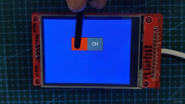
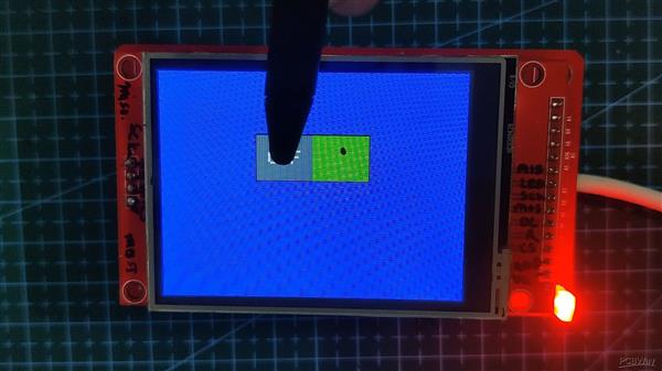
接下来是我修改的 ON-OFF Button Sketch,这样当按钮切换时,可以控制 LED 的状态。
// TouchCalData3Red btn hit Green btn hit 格式化文件系统 r 按指示触摸角将 REPEAT_CAL 设置为以再次停止此运行!校准完成! w ON OFF
波音球
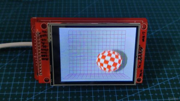
这是一个要求最高的草图,它充分利用了 ESP32 的处理能力,即 Boing Ball 动画草图。
它包含一个附加的头文件,该文件包含在代码部分中。
/bounceif(bally >= YBOTTOM) { 落地?巴利 = YBOTTOM; Clip ballvy = YBOUNCE; 弹起来 } /(by >= ) && (by < BALLHEIGHT)) { 在球位图区域内?是的,球合成数学... p = ball[by][bx1 / ]; 获取打包值(像素) c = (bx1 & ) ? (p & ) : (p ); 解压高或低 nybbleif(c == ) { 外球 - 只画网格 c = background[bgy][bgx1 / ] & ( >> (bgx1 & )) ? 网格颜色:BGCOLOR;} else if(c > ) { 在球区... c = palette[c]; } else { 在阴影区域... c = background[bgy][bgx1 / ] & ( >> (bgx1 & )) ? 网格阴影:BGSHADOW;} } else { 外球位图,只画背景位图... c = background[bgy][bgx1 / ] & ( >> (bgx1 & )) ? 网格颜色:BGCOLOR;} *destPtr++ = c<<
结论
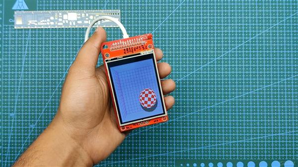
显示器通过载板与 ESP32 配合使用。
制作显示器驱动项目甚至为此显示器准备示例代码现在变得更加容易,因为我们正在使用适当的专用设置来对显示器进行编程。
目前,该项目已完成,目前不需要或不需要进一步改进。
至于它的使用,我正在准备一个项目,其中包括在这个显示器上运行动画,所以我将使用载板作为下一个项目的基础。
今天的内容就到这里了,如果您对这个项目有任何问题,请发表评论。
特别感谢 PCBWAY 对这个项目的支持,你们可以看看他们以更低的成本获得出色的 PCB 服务。
请继续关注下一个项目!
和平
声明:本文内容及配图由入驻作者撰写或者入驻合作网站授权转载。文章观点仅代表作者本人,不代表电子发烧友网立场。文章及其配图仅供工程师学习之用,如有内容侵权或者其他违规问题,请联系本站处理。 举报投诉
- 相关下载
- 相关文章


