
资料下载


带CMOS4511IC的RPi 7段显示器
分享资料个
描述
背景
在本系列的第一篇文章中,我讨论了一种直接通过 Raspberry Pi 2 驱动 7 段显示器的非常简单的方法。虽然这确实有效,但在实践中它有许多注意事项和限制。首先,通过每个 LED 的电流受限于 Raspberry Pi 上每个 GPIO 引脚可以提供的电流。其次,如果所有段都点亮,则进入 GPIO 输入引脚的累积电流超过了建议的输入电流。虽然我毫不怀疑 Raspberry Pi 可以处理它,但我不建议长期使用它。
介绍
为了改进上一篇文章并以更有效的方式驱动七段显示器,我将进行两项重大更改。首先,我将使用 CMOS4511 集成电路芯片从二进制输入驱动 7 段显示器。其次,为了保护 GPIO 输入晶体管将用于打开和关闭显示器,电路将接地而不是 GPIO 引脚。
先决条件
1 个树莓派 2
1 个 Cmos 4511 集成电路
4 x NPN 晶体管(或多或少取决于显示的位数)
1 x 5641AS 7 段显示器(或类似的 7 段显示器)
7 x 220 欧姆电阻
4 x 1 kOhm 电阻器(与晶体管数量相同)
弗里茨
电路
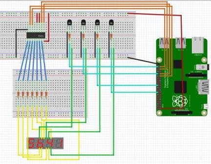
上面的 fritzing 图显示了演示中使用的完整电路。如果需要输出到 4511 和 GPIO,可以使用不同的 GPIO 引脚。
CMOS4511 IC 用于将二进制输入转换为 7 段显示输出。可以在数据表中找到 4511 的引脚分配。4个输入D0-D3接到树莓派上,7个输出a到g通过220欧姆电阻接显示器上相应的段。Vcc、BL、LT都要接电源[推荐3.3 v]和地应接地。LE 可以悬空。
从显示器上看,每个数字显示引脚都应连接到一个NPN晶体管的集电极,每个晶体管的发射极都可以接地。每个晶体管基极都可以通过一个 1 kOhm 电阻器连接到一个 GPIO 引脚。
代码
由于核心代码与以前的驱动程序相同,因此从以前的代码中抽象出我们的新驱动程序是有意义的。为此,我们需要做一些小改动。
首先,因为我们要使用 4 个引脚而不是 7 个引脚来驱动我们的显示器,我们需要覆盖现有类中的 SetDisplay 方法,因此现在应该将其设置为虚拟以允许我们执行此操作。我们还需要覆盖 ClearDisplay() 方法,因此它也被设置为虚拟的。
最重要的是,由于我们使用了一组不同的 GPIO 引脚,我们需要能够提供不同的构造函数,但由于我们不想使用原始的基本构造函数,因此我们必须提供另一个,在这种情况下无参数构造函数。因为我们只希望派生类能够使用它,所以我们可以将构造函数设置为受保护的。我们还可以利用此构造函数来设置先前在主构造函数中设置的取消标记,从而无需为这些字段提供受保护的访问器。
 protected Display()
{
this.cts = new CancellationTokenSource();
this.token = new CancellationToken();
}
我们需要对原始类做的最后一件事是使派生类可以访问显示数组
protected GpioPin[] Displays
        {
            get
            {
                return this.displays;
            }

            set
            {
                this.displays = value;
            }
        }
现在我们已准备好创建新的派生类。应该创建一个类似于我们原始基类的新构造函数,但我们只需要提供 4 个输出引脚 [for the 4511 D0-D3],然后是我们的显示引脚。然后根据基类执行引脚的初始化。
接下来我们可以提供重写的 SetDisplay 方法。此版本不是将提供的 int 转换为其 7 段表示形式,而是将提供的 in 转换为其二进制表示形式。
protected override void SetDisplay(GpioPin displayPin, int value)
        {
            this.ClearDisplay();

            switch (value)
            {
                case 0:
                    this.SetLow(new GpioPin[] { this.pinBcd0, this.pinBcd1, this.pinBcd2, this.pinBcd3 });
                    break;
                case 1:
                    this.SetHigh(new GpioPin[] { this.pinBcd0 });
                    this.SetLow(new GpioPin[] { this.pinBcd1, this.pinBcd2, this.pinBcd3 });
                    break;
                case 2:
                    this.SetHigh(new GpioPin[] { this.pinBcd1 });
                    this.SetLow(new GpioPin[] { this.pinBcd0, this.pinBcd2, this.pinBcd3 });
                    break;
                case 3:
                    this.SetHigh(new GpioPin[] { this.pinBcd0, this.pinBcd1 });
                    this.SetLow(new GpioPin[] { this.pinBcd2, this.pinBcd3 });
                    break;
                case 4:
                    this.SetHigh(new GpioPin[] { this.pinBcd2 });
                    this.SetLow(new GpioPin[] { this.pinBcd0, this.pinBcd1, this.pinBcd3 });
                    break;
                case 5:
                    this.SetHigh(new GpioPin[] { this.pinBcd0, this.pinBcd2 });
                    this.SetLow(new GpioPin[] { this.pinBcd1,this.pinBcd3 });
                    break;
                case 6:
                    this.SetHigh(new GpioPin[] { this.pinBcd1, this.pinBcd2});
                    this.SetLow(new GpioPin[] { this.pinBcd0, this.pinBcd3 });
                    break;
                case 7:
                    this.SetHigh(new GpioPin[] { this.pinBcd0, this.pinBcd1, this.pinBcd2 });
                    this.SetLow(new GpioPin[] { this.pinBcd3 });
                    break;
                case 8:
                    this.SetHigh(new GpioPin[] { this.pinBcd3 });
                    this.SetLow(new GpioPin[] { this.pinBcd0, this.pinBcd1, this.pinBcd2 });
                    break;
                case 9:
                    this.SetHigh(new GpioPin[] { this.pinBcd0, this.pinBcd3 });
                    this.SetLow(new GpioPin[] { this.pinBcd1, this.pinBcd2 });
                    break;
                case 10:  // Clear Display
                    this.SetHigh(new GpioPin[] { this.pinBcd0, this.pinBcd1, this.pinBcd2, this.pinBcd3 });
                    break;
                default:
                    this.SetHigh(new GpioPin[] { this.pinBcd0, this.pinBcd1, this.pinBcd2, this.pinBcd3 });
                    break;
            }

            this.SetHigh(new GpioPin[] { displayPin });
        }
此方法还有一个变化。也就是说,这次我们将 GPIO 设置为高电平,而不是将 GPIO 引脚设置为低电平来打开显示数字。这是因为我们现在不是将引脚设置为低电平以允许电流流入 GPIO 引脚,而是将引脚设置为高电平,然后“切换”允许电流流动并下沉至接地轨的晶体管。正是出于这个原因,我们还覆盖了 ClearDisplays 方法以将所有 GPIO 引脚设置为低 [而不是高]。
 protected override void ClearDisplay()
{
this.SetLow(this.Displays);
}
声明:本文内容及配图由入驻作者撰写或者入驻合作网站授权转载。文章观点仅代表作者本人,不代表电子发烧友网立场。文章及其配图仅供工程师学习之用,如有内容侵权或者其他违规问题,请联系本站处理。 举报投诉
- 相关下载
- 相关文章


