资料下载

降低串扰的DirectPath耳机放大器
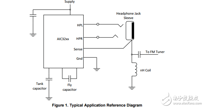
Figure 1 is commonly used in most mobile phones and tablets. The headphone cable is also used as an FM antenna.
The amplifier sets a bias output signal riding on the voltage sensed by the sense pin. With this technique and Kirchhoff’s current law, Figure 1 is analyzed. Assume a sine wave signal is applied to only on the HP (Head Phone) left output. The current that returns to ground during positive sine wave cycle causes a voltage drop across the nH coil. Thus, the sense pin has some voltage sensed instead of clean ground potential of 0V. The HP amplifier right output contains this small signal. Thus, a right ear headphone load that is connected to the jack has both terminals swinging simultaneously causing the potential difference to be zero, and hence, no audible output - no crosstalk. The same is true when the signal is playing only on the HP right channel.

声明:本文内容及配图由入驻作者撰写或者入驻合作网站授权转载。文章观点仅代表作者本人,不代表电子发烧友网立场。文章及其配图仅供工程师学习之用,如有内容侵权或者其他违规问题,请联系本站处理。 举报投诉
- 相关下载
- 相关文章


