
资料下载


太阳能WiFi气象站 V3.0开源
李晶
分享资料个
PCB图如下: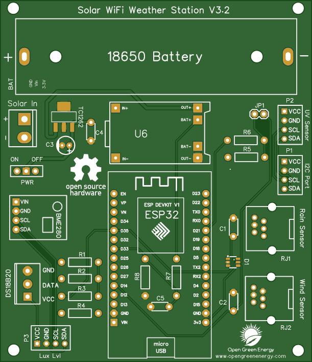
Description
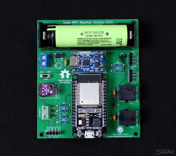
Solar Powered WiFi Weather Station V3.0
This Weather Station is such compact weather station that consists of several meteorological sensors that measure the following parameters:
1. Internal Temperature (BME280)
2.Humidity (BME280)
3. Barometric Pressure (BME280)
4.External Temperature (DS18B20)
5. Wind Speed ( Sparkfun Weather Meter )
6. Wind Direction ( Sparkfun Weather Meter )
7. Rain Gauge ( Sparkfun Weather Meter )
8. UV Index ( SI1145)
9. Lux Level ( BH1750 )
I have designed a customized PCB for this project. It is designed in such a way that you can conveniently integrate different combinations of sensors according to your actual application needs.
Why a Weather Station?
Imagine you are residing at a place that is far away from the meteorological department. In such a case, the weather predictions you get may not be the most precise. This is where home weather stations become more advantageous. This small weather station can provide accurate data regarding the weather parameters of where you live.
Today, data on localized weather, known as microclimates, is the new frontier for more precise and accurate weather forecasting. As a result, the collection of weather data is becoming increasingly smaller and gridded.
Applications:
The applications of this type of small portable weather station are vast in the area of smart agriculture, smart city, solar power plants, construction site, etc.
Update On 24.05.2021
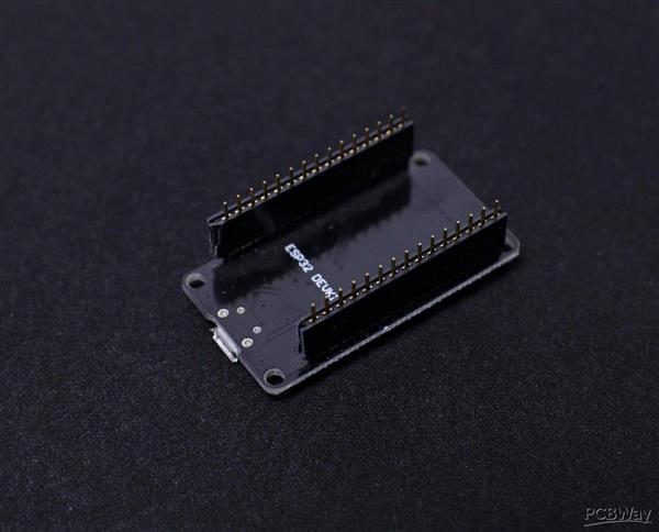
Now You can order the fully assembled PCB V3.0 from PCBWay. Please note that no sensors are included in the PCB, but you will get an ESP32 dev board and a Solar panel in the package.
Video Tutorial:
Components Used:
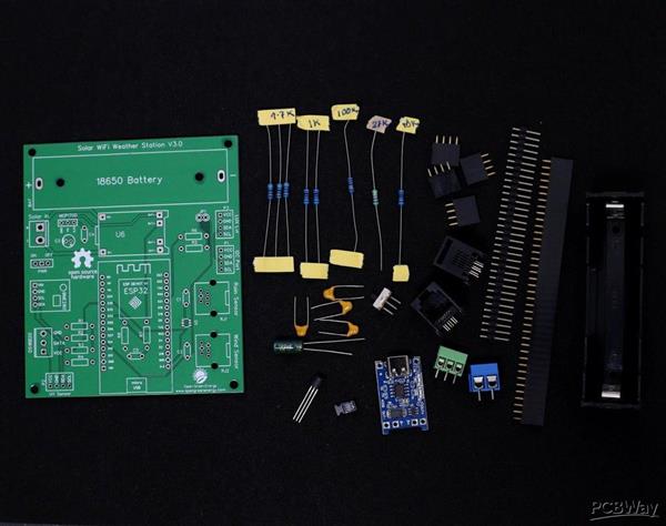
Components Used:
1. ESP32 Dev Kit V1- 30 Pins ( Aliexpress / Banggood )
2. TP4056 ( Aliexpress / Banggood )
3. Barometric Pressure sensor BME280 ( Amazon / Banggood )
4. Temperature Sensor - DS18B20 ( Amazon / Banggood )
5. UV Index Sensor - GY1145 ( Amazon / Banggood )
6. Lux Level Sensor - BH1750 ( Amazon / Banggood )
7. Wind & Rain Sensor ( Amazon / Sparkfun )
8. MCP1700-3.3V ( Amazon)
9. Resistors - 2 x 1K, 1 x 10K, 3 x 4.7K, 1 x 27K, 1 x 100K ( Amazon / Banggood )
10. Electrolytic Capacitor - 1 x 100uF ( Amazon / Banggood )
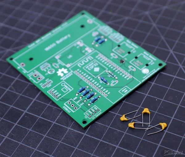
11. Ceramic Capacitors - 4 x 0.1uF ( Amazon / Banggood )
12. TVS Diode - DT1042-04SO ( Amazon ) - Optional
13. RJ11 Connector ( Aliexpress )
14. Male / Female Headers ( Amazon / Banggood )
15. Jumper Cap ( Amazon / Banggood )
16. Screw Terminal-2P - 5.08mm pitch ( Amazon / Banggood )
17. Screw Terminal -3P -3.5mm pitch ( Sparkfun )
18. Solar Panel - 5V / 1.2Watt ( 110 x 69 mm ) - ( Amazon / Aliexpress / Banggood )
19. 18650 Battery ( Banggood )
20. 8650 Battery Holder ( Amazon / Banggood )
21. 22 AWG Wires ( Amazon / Banggood )
22. Jumper Wires M-F( Amazon / Banggood )
23. Slide Switch ( Amazon / Banggood )
24. PCB ( PCBWay )
Tools Used:
1. Soldering Iron ( Amazon / Banggood )
2. Nipper ( Amazon / Banggood)
3. Wire Stripper ( Amazon / Banggood)
4. 3D Printer ( Amazon / Banggood)
Update On 01.05.2021
The PCB V3.0 is updated to V3.1, a small change in the I2C ports ( P1, P2, and P3 )
The sequence of pins are changed from ( VCC, GND, SDA, SCL ) to ( VCC, GND, SCL, SDA )
Note: The PCB V3.0 is working perfectly, but you need extension wires to connect the sensor modules in ports P1, P2, and P3.
Download the Gerber files for PCB V3.0 from Instructables Step-14
Step 1: Selecting the Power Supply
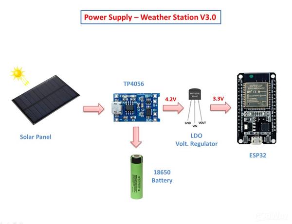
If you are planning to install the weather station at a remote location like your farmhouse, you may not get access to the power grid to run the weather station. To run the station continuously, there must be a continuous power supply otherwise the system will not work. The best way to provide continuous power to the circuit is by using a battery. But in the case of the battery, after some days of run, its juice will run out, and it is a really difficult job to go there and charge it. So a solar charging circuit was proposed to use free energy from the sun to charge the battery and to power the ESP32 board.
Here, I have used a 18650 Li-Ion battery. The battery is charged from a Solar panel through a TP4056 charging module. The TP4056 module comes with a battery protection chip or without the protection chip. I will recommend buying a module that has a battery protection chip included.
The 18650 battery outputs 4.2V when fully charged. The battery voltage is further step down to 3.3V by using a low dropout voltage regulator(MCP1700-3302E).
The output from the voltage regulator will power the ESP32 through the 3.3V pin.
Step 2: Power Supply Circuit
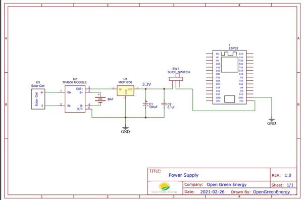
The operating voltage of the ESP32 is 3.3V whereas the fully charged battery voltage is 4.2V. So we have to step down the battery voltage from 4.2V to 3.3V, which can easily be done by a linear voltage regulator but unfortunately, it is not at all recommended for this project. Because all the linear regulators require an input voltage at least some minimum amount higher than the desired output voltage. That minimum amount is called the dropout voltage. Due to this reason when battery voltage drops to around 3.7V, the linear voltage regulator will not be able to maintain the voltage required voltage ( 3.3V ).
The solution to the above problem is to use a low-dropout or LDO regulator. A low-dropout or LDO regulator is a DC linear regulator which can regulate the output voltage even when the supply voltage is very close to the output voltage. Here we will use an MCP1700 LDO for efficiently powering the Circuit.
A ceramic capacitor ( 0.1uF) and an electrolytic capacitor (100uF) are connected in parallel to the GND and Vout pin of the LDO ( MCP1700 -3.3V ) to smooth the voltage peaks.
The output of the MCP1700 is connected to the ESP32 3.3V pin through a slide switch.
MCP1700 Data Sheet: Download
Step 3: Wind Vane ( Wind Direction Sensor)
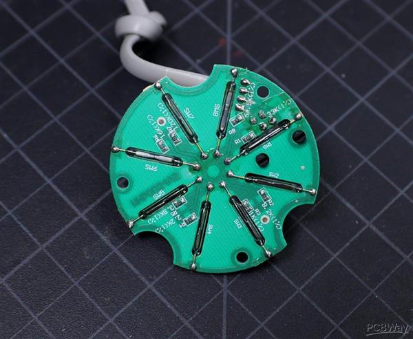
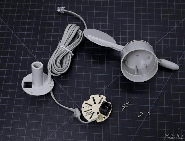
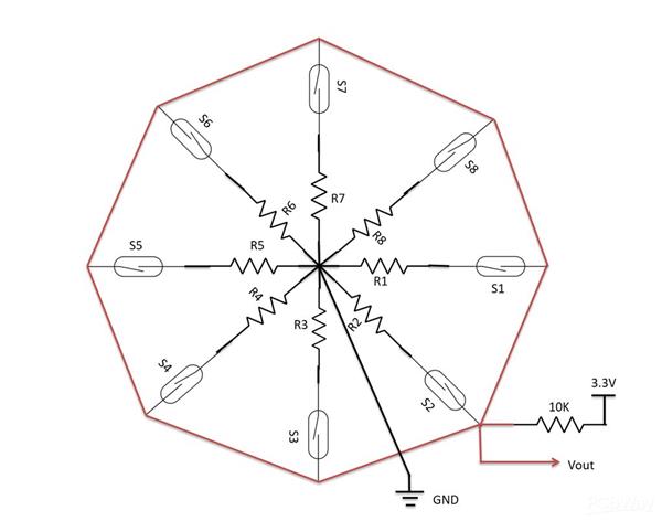
The wind vane indicates the direction that the wind is blowing. It is the most complex of the sensors in the Sparkfun Weather Sensor Kit. It has eight reed switches, each connected to a different resistor. As the wind vane rotates, a magnet closes the reed switches and may close two at a time due to their proximity to each other, allowing up to 16 different positions to be indicated. However, in testing the unit, I never could make the device close two switches at once, so although it might be possible theoretically to measure 16 directions, I only get eight. The software takes 16 directions into account, just in case.
An external resistor can be used to form a voltage divider, producing a voltage output that can be measured with an analog to digital converter, on your the microcontroller allows you to determine the direction of the wind vane pointer.
To measure voltage output, I have used a 10kohm external resistor to form a voltage divider with the wind vane resistor ( Rvane). The 10K resistor is connected to 3.3V as shown in the above figure. Then, I connect the middle of the divider to the ESP32 ADC pin (GPIO 35), measure the voltage, and by referring to the table shown above, convert to the wind direction.
The reed switches and resistors arrangement are shown in the above picture. Resistance values for all 16 possible positions are given in the table.
When the wind vane pointer falls in between two switches, the resistance value is considered as the equivalent resistance between the two adjacent resistances. In this situation, the vane’s magnet activates two switches simultaneously, as result they are connected in parallel.
Step 4: Anemometer ( Wind Speed Sensor)
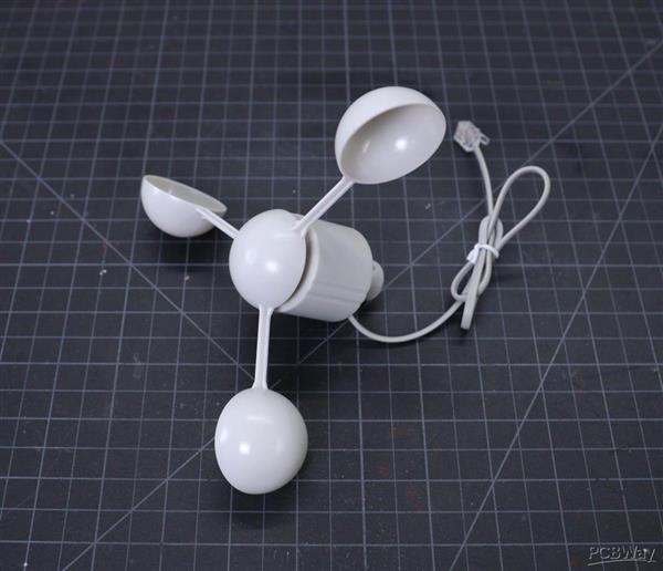
The wind speed sensor is a cup-type anemometer measures wind speed by closing a contact as a magnet moves past a reed switch. As per the datasheet, a wind speed of 2.4km/h (1.4912 mph) causes the switch to close once per second. The anemometer switch is connected to the inner two conductors of the RJ 11 cable shared by the anemometer and wind vane (pins 2 and 3).
The Anemometer is connected to the ESP32 GPIO pin 14 and GND. After that, all we need to do then is to monitor for button presses which is pretty straightforward. We can use the pin interrupts method to monitor the button press ( tips). When the reed switch closes the circuit (pressing the button), it triggers a software event.
If you want to make your own wind sensor, then read this nice Instructable
These are few more 3D printed Wind Sensors:
1. Anemometer
2. Wind Speed Gauge
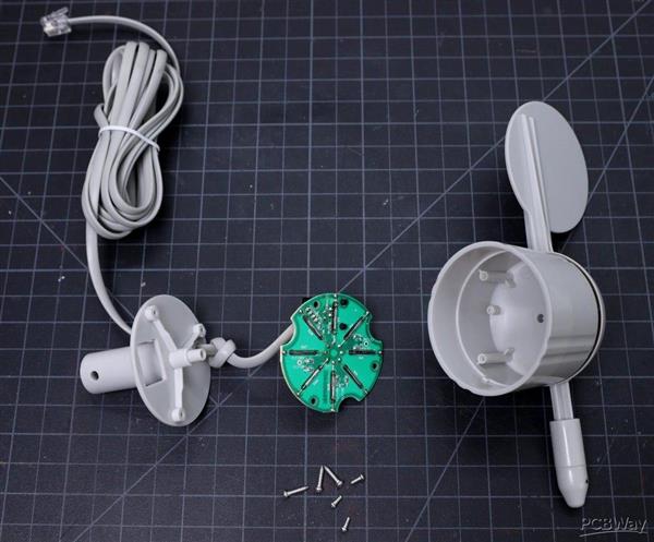
Step 5: Rain Gauge ( Rain Fall Sensor )
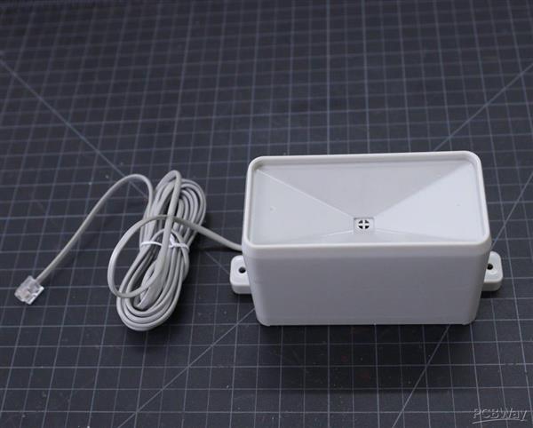
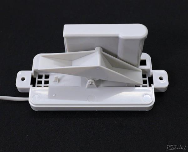
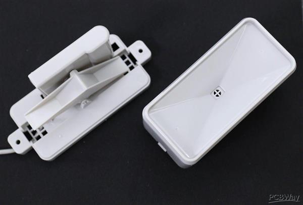
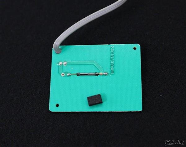
Here I have used a most common type of Rain Sensor which is called a Tipping Bucket rain gauge. Basically, there's a little see-saw shape tipper bucket inside the sensor ( see the above picture ). The rain fills up a bucket on one end and it tips over so that it empties and the bucket on the other side starts to fill. Each time the bucket tips it passes a magnet over a reed switch making a momentary electrical connection. The buckets are calibrated to a volume of water, which means if we can count how many times the switch closes we can calculate how much rainfall there's been.
Much like the wind speed gauge, the rainfall gauge generates ticks to tally the amount of rain that has fallen. Count ticks to determine how much rain has fallen recently. Each tick represents 0.011" ( 0.28mm ) of rainfall. This sensor is connected to pin 25 of the ESP32.
The rain gauge that I have used here is from Sparkfun. It has an RJ-11 plug on the end, you can directly plug it into the Weather Station V3.0 PCB.
You can make your 3D printed Rain Gauge by following this article
Step 6: Measuring the Rainfall
In the previous step, we have discussed that each time the bucket tips, it passes a magnet over a reed switch making a momentary electrical connection. Here each tip of the bucket in the rain gauge can be assumed as a button press. We can easily then connect the gauge as if it were a button.
The rain gauge is connected to the ESP GPIO pin 25 and GND. After that, all we need to do then is to monitor for button presses which is pretty straightforward. We can use the pin interrupts method to monitor the button press ( tips). When the reed switch closes the circuit (pressing the button, the bucket tipping), it triggers a software event.
Here I am using attachInterrupt()to monitor the number of tips. You can find the details from Arduino Page.
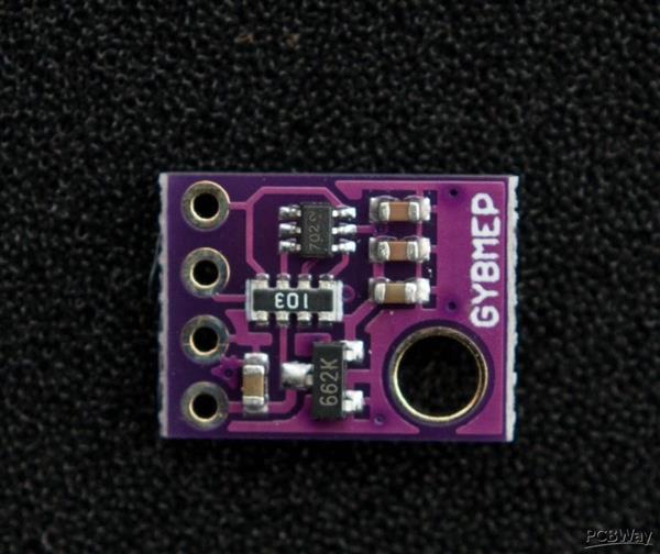
Step 7: Monitoring Pressure, Temperature and Humidity by BME280
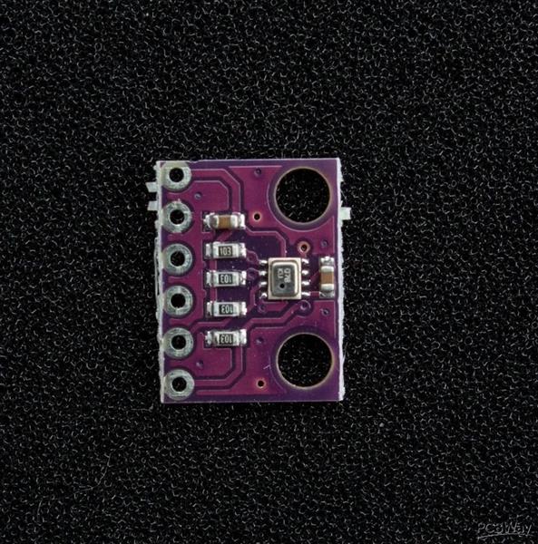
In the earlier days, weather parameters like ambient temperature, humidity, and barometric pressure were measured with separate analog instruments: thermometer, hygrometer, and barometer. But today the market is flooded with cheap and efficient digital sensors that can be used to measure a variety of environmental parameters. The best examples are sensors like DHT11, DHT 22, BMP180, BMP/E280, etc.
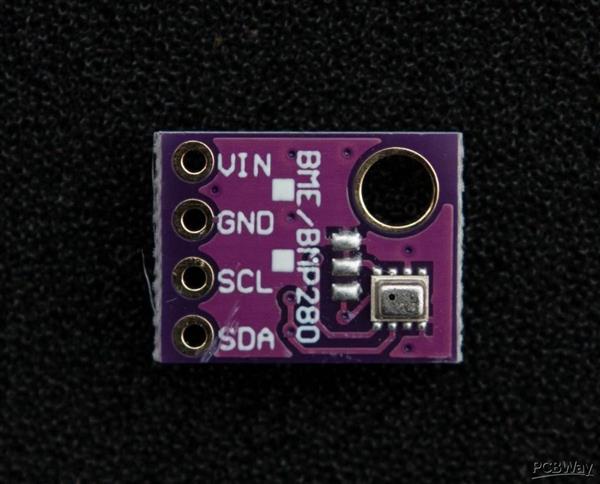
In this project, we will use BMP280 / BME280 sensor.
BMP280:
BMP280 is a sophisticated sensor that very accurately measures barometric pressure and temperature with reasonable accuracy. The BME280 is the next generation of sensors from Bosch and is the upgrade to the BMP085/BMP180/BMP183 - with a low altitude noise of 0.25m and the same fast conversion time. The advantage of this sensor is that it can use either I2C or SPI for communication with the microcontroller. For simple easy wiring, I will suggest buying the I2C version board.
BME280:
The new BME280 sensor, an environmental sensor with temperature, barometric pressure, and humidity. The BME280 is the next generation of sensors from Bosch and is the upgrade to the BMP280. This precision sensor from Bosch is the best low-cost sensing solution for measuring humidity with ±3% accuracy, barometric pressure with ±1 hPa absolute accuracy, and temperature with ±1.0°C accuracy. It can be used in both I2C and SPI.
Note:
BME280 can measure humidity but BMP280 can't. In the market, BMP280 is also available by the name of BME280. So be sure whether it is a BMP280 or BME280.
You can read this nice article on BME280 for a better understanding.
Step 8: Monitoring UV Index - SI1145 Sensor
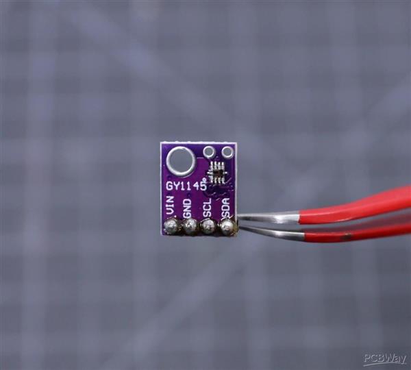
The Si1145 is a sensor with a calibrated UV sensing element that can calculate the UV Index. It can communicate via I2C communication (address 0x60). You can hook up this sensor with I2C port in the PCB which is located at the bottom left of the ESP board.
The SI1145 sensor really doesn’t have an actual UV sensor! Instead, it looks at the amount of visible and IR light it receives from the Sun and uses a formula to calculate the UV index, right down to two decimal points.
You can read this article to know more about the UV sensor.
If you need a more accurate measurement of UV Index, you may use the VEML6070 sensor. Unlike the Si1145, this sensor will not give you UV Index readings. However, the Si1145 does UV Index approximations based on light level, not true UV sensing. The VEML6070 in contrast does have a real light sensor in the UV spectrum.
You can read this tutorial for writing the code and using its library.
Step 9: Monitoring Lux Level - BH1750 Sensor
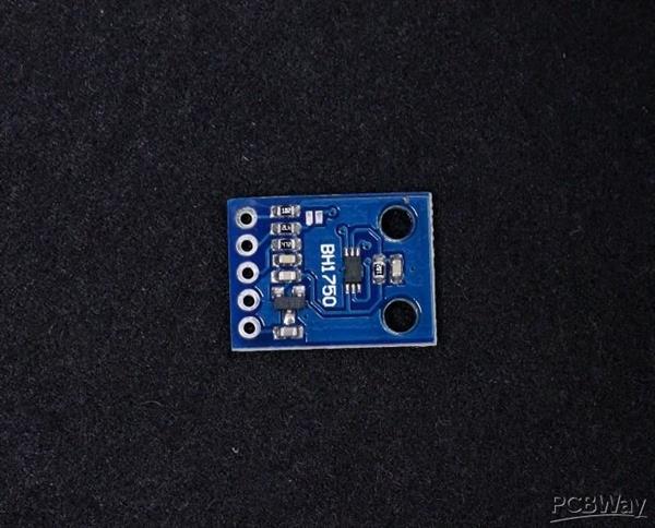

The BH1750 Ambient Light Sensor Module is based on the digital Ambient Light Sensor IC BH1750FVI developed by ROHM Semiconductor. It is a digital IC with built-in 16-bit illuminance to digital converter.
The output of this sensor is in LUX (lx), so it does not require any further calculations. Lux is the unit to measure Light intensity. It measures the intensity according to the amount of light hitting on a particular area. One lux is equal to one lumen per square meter.
For communication with external devices like ESP32, the BH1750 Ambient Light Sensor IC uses I2C Bus Interface.
Pin Description
VCC – 3.3V to 3.3V
GND – VCC
SCL – SCL
SDA – SCL
ADD – I2C Device Address ( Kept Open )
You can read this instructable for information on BH1750 light sensor
Step 10: External Temperature Sensor
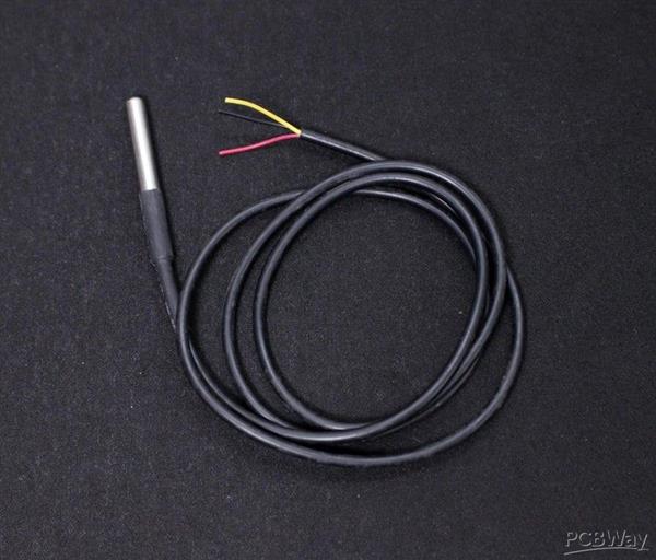
If you need, you can connect an external temperature sensor like DS18B20 to monitor the ambient temperature. DS18B20 is One Wire interface Temperature sensor manufactured by Dallas Semiconductor Corp. It requires only one digital pin for two-way communication with a microcontroller. I have hooked up this sensor with ESP32 GPIO pin4.
The DS18B20 comes usually in two form factors. One that comes in the TO-92 package looks exactly like an ordinary transistor and another one in a waterproof probe with an extension cable. I have used DS18B20 probe for measuring the temperature. It uses a one-wire protocol to communicate with the ESP32. It can be hooked up to the 3 pin screw terminal on the PCB.
To interface with the DS18B20 temperature sensor, you need to install the One Wire library and the Dallas Temperature library. You can read this article for more details on the DS18B20 sensor.
Step 11: Monitoring Battery Voltage
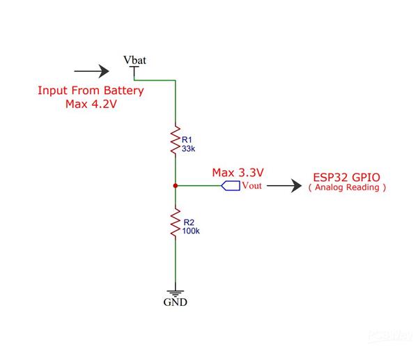
The weather station is run by a 18650 Li-Ion battery, so it is essential to monitor the battery status. The max voltage input to the ESP32 board is around 3.2~3.3V but a fully charged 18650 battery voltage is 4.2V. So to measure this voltage we have to step down the voltage by using a voltage divider network.
The voltage divider is made up of 27k (R1) and 100k (R2).
When you have your ESP32 powered with batteries or solar-powered as in this case, it can be very useful to monitor the battery level. One way to do that is to read the output voltage of the battery using an analog pin of the ESP32.
However, the battery we’re using here outputs a maximum of 4.2V when fully charged, but the ESP32 GPIOs work at 3.3V. So, we need to add a voltage divider so that we’re able to read the voltage from the battery.
The voltage divider formula is as follows:
Vout = (Vbat*R2)/(R1+R2)
So, if we use R1=27k Ohm, and R2=100k Ohm,
We get: 1 Vout = (4.2*100k)/(27k + 100k) = 3.307V
So, when the battery is fully charged, the Vout outputs 3.307V that we can read with an ESP32 GPIO pin. To select the voltage divider resistance values, you can use this online calculator.
Step 12: ESP32 - Thingspeak-Deep-Sleep
The heart of our Weather Station is an ESP8266 SOC which is a power-hungry chip. When your project is powered by a plug-in the wall, you tend not to care too much about power consumption. But if you are going to power your project with batteries, every mA counts.
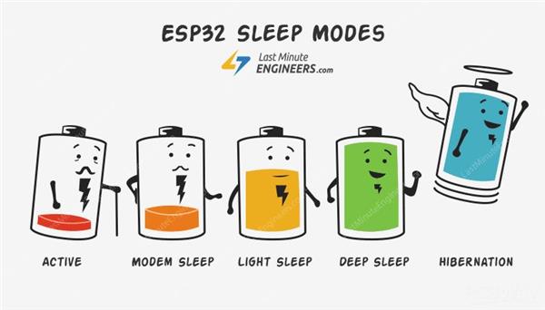
Our objective is to run the device by using a 18650 Li-Ion battery. To run the ESP32 by using a battery, we have to lower the power consumption. To do that, we’ll use the Deep Sleep Mode which is the most power-efficient option for the ESP chip. It allows to put the ESP32 into hibernation and saves the battery. You can wake up the ESP at regular intervals to make measurements and publish them.
Calculating Battery Life:
The ESP32 consumes around 75mA in normal operation and hits about 150mA while transmitting data over WiFi. and in Deep Sleep about 10uA. The ESP32 takes ~ 30secs to upload data.
Battery Life calculations:
Battery Used: 3400mAh / 3.7V 18650 Li-Ion
Publish Interval = 10mins ( ON Time: 30 sec and Sleep Time: 9 mins 30 sec )
Total number of Readings / Hour = 60/10 = 6
Power consumption per hour (ON time) = 6 x 150 mA * 30 / 3600 = 7.5mA
Sleep time = 6 x 10uA * 570 / 3600 = 0.0095 mA
Total time in hours on battery = 3400 / (7.5+0.0095) = 452.76Hrs
Total days on battery = 452.76/24 = 18.86 Days
Image Credit: lastminuteengineers.com
Step 13: Solar Panel Selection
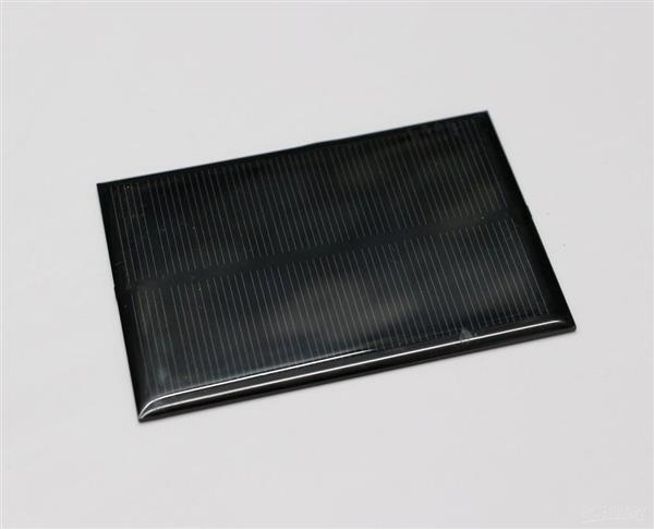
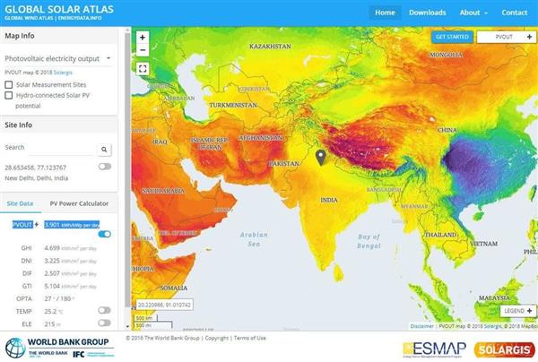
The amount of solar insolation varies according to which part of the globe you are located at. To find out the amount of solar insolation in your area, you can use the Global Solar Atlas. By taking consideration into a minimum of 1 hour of full sunlight, we are going to select the solar panel.
From the previous step, it is concluded that the average current consumption is 7.5 mA
Charge required for running the device for the whole day = 7.5 mA x 24 Hours = 180 mAh
So, our target is to generate 180 mAh in 1 hour.
To charge a 3.7V Li-Ion battery, a solar panel of voltage 5 to 6V is adequate.
Required Solar Panel rating = 180 mA at a voltage of around 5 to 6 volts.
Solar panel rating = 180 mA x 5V = 0.9 Watt, by considering some losses, I have selected a higher rating solar panel.
Solar Panel Selected: I have used a 5V,250mA Solar Panel ( 110 x 69 mm)
Step 14: PCB Design
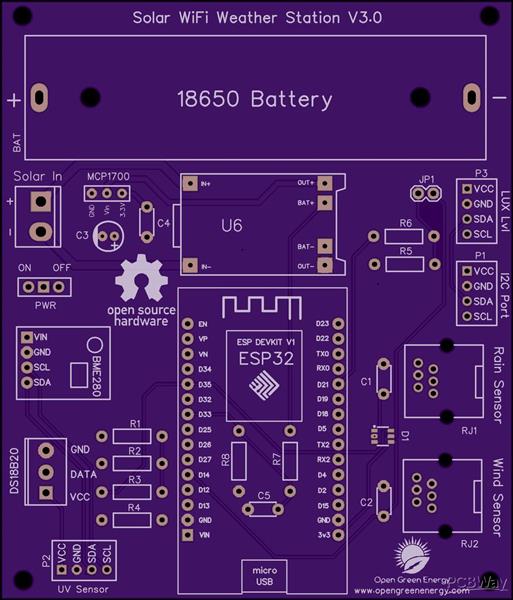
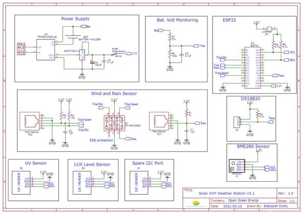
I have drawn the schematic by using EasyEDA online software after that switched to PCB layout.
All of the components you added in the schematic should be there, stacked on top of each other, ready to be placed and routed. Drag the components by grabbing on its pads. Then place it inside the rectangular borderline.
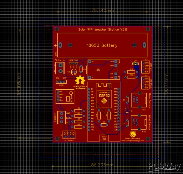
Arrange all the components in such a way that the board occupies minimum space. The smaller the board size, the cheaper will be the PCB manufacturing cost. It will be useful if this board has some mounting holes on it so that it can be mounted in an enclosure.
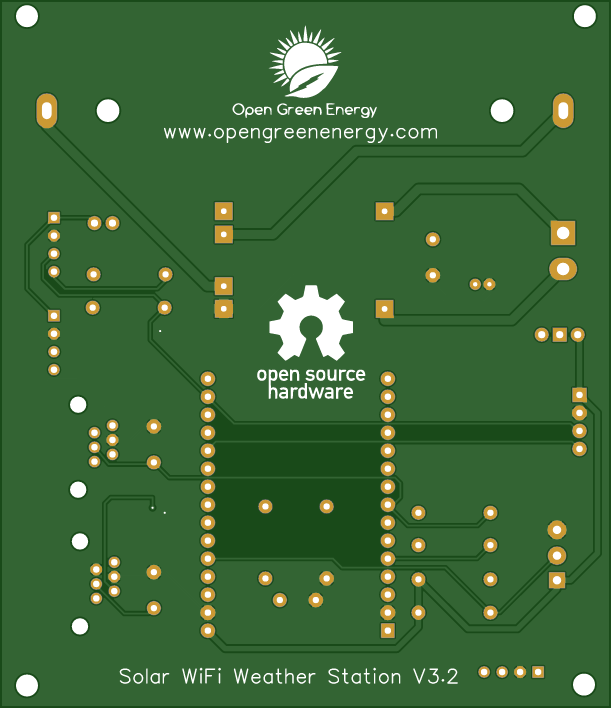
Now you have to route. Routing is the most fun part of this entire process. It’s like solving a puzzle! Using the tracking tool we need to connect all the components. You can use both the top and the bottom layer for avoiding overlap between two different tracks and making the tracks shorter.
You can use the Silk layer to add text to the board. Also, we are able to insert an image file, so I add an image of my website logo to be printed on the board. In the end, using the copper area tool, we need to create the ground area of the PCB. Now the PCB is ready for manufacturing.
You can order it from PCBWay
Note: When you place an order, I will get 10% donation from PCBWay for contribution to my work. Your little help may encourage me to do more awesome work in the future. Thank you for your cooperation.
Update On 24.05.2021
Now You can order the fully assembled PCB V3.0 from PCBWay. Please note that no sensors are included in the PCB, but you will get an ESP32 dev board and a Solar panel in the package.
Update on 01.05.2021
The PCB V3.0 is updated to V3.1, a small change in the I2C ports ( P1, P2, and P3 ) The sequence of pins are changed from ( VCC, GND, SDA, SCL ) to ( VCC, GND, SCL, SDA ) Note: The PCB V3.0 is working perfectly, but you need extension wires to connect the sensor modules in ports P1, P2, and P3.
Update on 09.09.2021
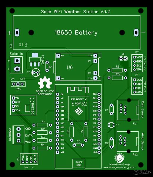
The PCB V3.1 is updated to V3.2, upgrade from 200mA LDO ( MCP1700 ) to 500mA LDO ( TC1262-3.3V ) to make the power supply more stable. You can download the Gerber files or buy the PCB V3.2 from PCBWay
You can download the earlier Gerber files for PCB V3.0 and V3.1 from PCBWay.
Step 15: PCB Fabrication
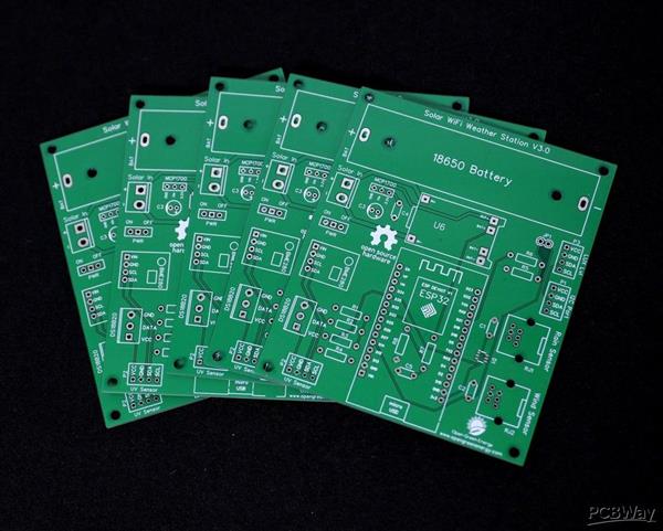
Once we are completed the PCB design we just need to click the “Gerber Output” button, save the project and we will be able to download the Gerber files which are used to manufacturing the PCB.
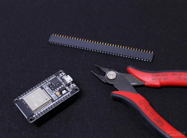
Step 16: Assembling the PCB
After receiving the board from the PCB fab house, you have to solder the components. For Soldering, you will need a decent Soldering Iron, Solder, Nipper.
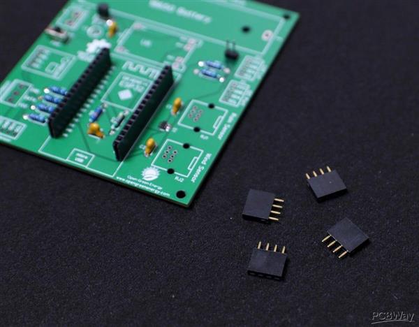
First I cut the straight male and female headers pin for ESP32 Board, TP4056, BME280, and jumper JP1. Following are the details about the headers :
1. ESP Board - 2 x 15pins ( Female )
2. BME280 - 1 x 4pins ( Female )
3. UV Sensor - 1 x 4pins ( Female )
4. Lux Level Sensor - 1 x 4pins ( Female )
5. Spare I2C Port - 1 x 4pins ( Female )
4. Jumper JP1- 1 x 2pins ( Male )
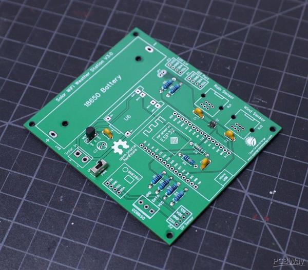
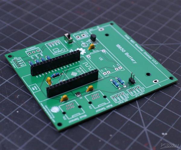
It is good practice to solder the components according to their height. Solder the lesser height components first. I have started by soldering the resistors, switch and then moved towards the bigger components like headers pin, screw terminal, and battery holder.
Step 17: Soldering the TVS Diode
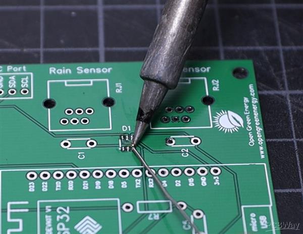
In the entire PCB, the lesser height component is the TVS diode which is the only SMD component used in this project. You can see the datasheet.
First, apply soldering flux on all 6 pads and then apply a small amount of solder to the corner pads. Place and align the diode chip using tweezers. Hold the chip in place while touching the pads with the tip of the soldering iron so that the solder melts the pin and the pad together.
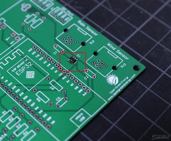
Be sure the dot symbol on the PCB and the TVS diode is matching together. The dot symbol represents pin number -1.
Now apply solder to all the pads, and you are done. If you mess up during the soldering, you can remove the extra solder by using a desoldering wick.
You can read this tutorial if you are new to soldering SMD components by using a soldering iron. By the way, I am also learning.
Note: Without the use of this TVS diode not affect the functionality of the weather station, it provides additional protection to the circuit.
Step 18: Soldering the Resistors and Ceramic Capacitor
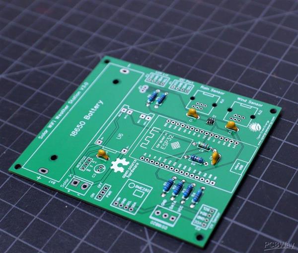
By considering the component height, after the TVS diode, the next component is the resistor and then ceramic capacitors. Bend the resistor legs and insert them into the PCB holes. Solder the legs and trim the extra legs by using a nipper.
During soldering always refer to the schematic diagram to avoid any mistakes. The schematic diagram is attached below. You should take a printout and keep it side when soldering.
Similarly, solder the ceramic capacitors. Note that ceramic capacitors do not have any polarity, so you can solder in any way, it will work.
Step 19: Soldering the LDO MCP1700
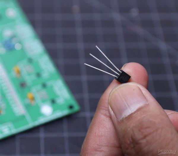
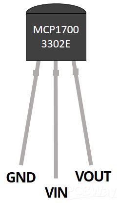
The LDO MCP1700 used in this project comes in the TO92 package in which the pin-to-pin distance is only 1.26mm. So if you are a beginner, you may short the pads during the soldering, to avoid this I have not used the TO92 package footprint on the PCB. I intentionally provided some gaps in between the soldering pads.
Stretch the 3 legs of MCP1700 as shown in the above picture, then insert it into the PCB holes where it is labeled as MCP1700.
The pinout diagram is shown above, each pin name is also labeled on PCB so that you will not confuse during the soldering.
Step 20: Trim the Headers
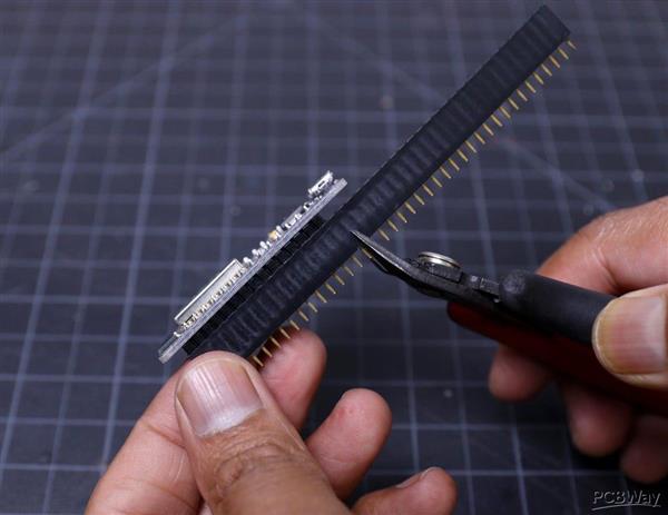
The best way to trim the female header pieces is to count out 15 pins, pull the 16th pin, then use a nipper to cut the gap between the 15th and 17th pin.
You must be careful when cutting the header to center your snip. An off-center cut may result in the mechanical portion of the header escaping or losing some of its retention force.
Optionally, you may take a file, piece of sandpaper to sand down the end of the header so that it will look very smooth.
I followed the above principle to prepare all the female headers.
Step 21: Soldering the Headers
Plug all four headers into the PCB. The PCB is labeled to identify which header goes to which place. The male pins of the header should enter the top side of the PCB and extend out the bottom. I always solder two end pins first, then solder the remaining pins.
It's important that each of the headers is at a nice, 90° angle to the PCB. This will ensure that the ESP32 board/ sensor modules will slide straight onto the headers, and you won't have to bend any pins in doing so.
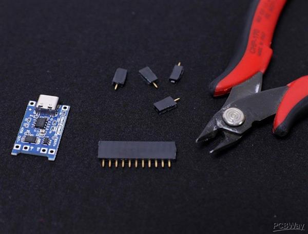
To mount the TP4056, here I have used 6 x 1 female pin, you may use male pins too.
Trim the extra legs by using a nipper.
Step 22: Soldering the Bigger Components
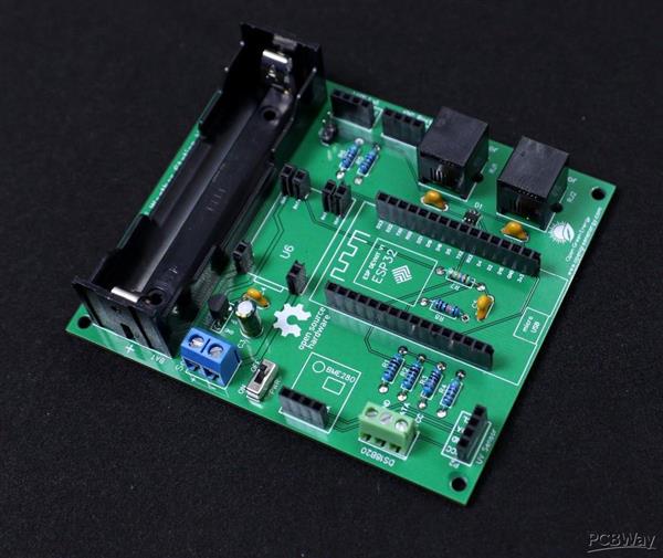
The bigger components on the PCB are the terminal connectors ( two screw terminals and two RJ11 connectors) and the 18650 battery holder. First solder the two screw terminals then solder the RJ11 connector. The RJ11 connector has some locking arrangement, you have to insert it into the two side holes on the PCB.
Step 23: Adding the Modules and Battery
After assembling the header pins, switch, Connectors, and screw terminal, it is time to insert the boards into their respective headers. The headers are clearly labeled on the PCB, so there is no chance of confusion.
First I place the TP4056 board and solder all the pads.
Then I added the ESP32 Board and BME280 Sensor.
Finally, I inserted the 18650 battery into the battery holder.
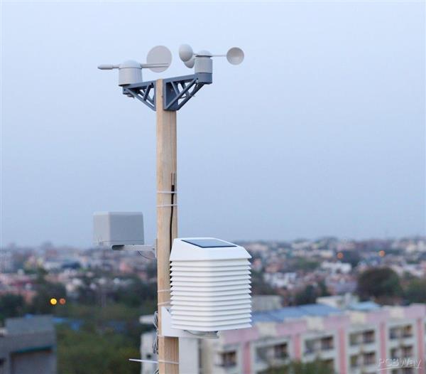
Step 24: 3D Printed Enclosure
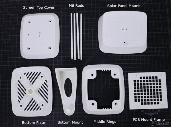
The ideal enclosure for keeping the weather sensors is the Stevenson Screen. A Stevenson screen is an enclosure to shield meteorological sensors against precipitation and direct heat radiation from outside sources, while still allowing air to circulate freely around them.
My friend Glen from New Zealand helped me to make this professional-grade Stevenson Screen. I really appreciate his help in making this project successful.
This has a simple wall mount and a 2 part cover to isolate the heat transfer from the solar panel. The V3.0 design has a provision for mounting a UV Index sensor on the top. Apart from this, the top cover for mounting solar panel is kept away from the main enclosure to avoid heat transfer from the solar panel to the interior part of the enclosure.
The Stevenson Screen has 6 parts:
1. PCB Mount Frame
2. Bottom Plate
3. Bottom Mount
4. Middle Rings x 12 Nos
5. Screen Top Cover
6.Top Cover for Solar Panel Mount ( Solar Panel Size: 110 x 69 mm )
7. M6 Rod x 4 Nos
I used my Creality 3D printer and 1.75 mm white PLA filament to print the parts. I will recommend using ABS or PTEG filament instead of using PLA.
You can refer to the above explosion diagram to assemble the 3D printed parts.
You can download the .STL files from Thingiverse
You can download the STEP files from GRABCAD for any modification.
Code
Software
Weather_Station_V3_30.03.2021.ino
Download(108)
Circuit diagrams and Schematics
https://www.instructables.com/Solar-Powered-WiFi-Weather-Station-V30/
Schematic Diagram
Schematic_Weather+Station_V3.0 .pdf
Download(86)
CAD-Custom parts and enclosures
3D Printed Enclosure .STL Files
FNMIANEKMHQR0ZG.jpg
Download(26)
声明:本文内容及配图由入驻作者撰写或者入驻合作网站授权转载。文章观点仅代表作者本人,不代表电子发烧友网立场。文章及其配图仅供工程师学习之用,如有内容侵权或者其他违规问题,请联系本站处理。 举报投诉
- 相关下载
- 相关文章


