
资料下载

带有Netduino的C#智能物联网交换机
描述
智能物联网交换机
我研究这个话题已经有一段时间了(看看我以前的项目)。我是物联网的忠实粉丝,尤其是家庭自动化。这些应用程序有可能带来社会和生活水平的巨大变化。猜猜看,我必须通过一个新平台应用物联网:C#感谢 Wilderness Labs。
让我们开始吧!
1. 所需材料
- Netduino 3(以太网或 WiFi)
- 继电器模块(我在这个项目中使用了 2 通道继电器)
- 原型面包板
- DHT11 用于温度监测。
- Android 设备(运行 Xamarin 应用程序)
- 盒子(我用的是木制的)
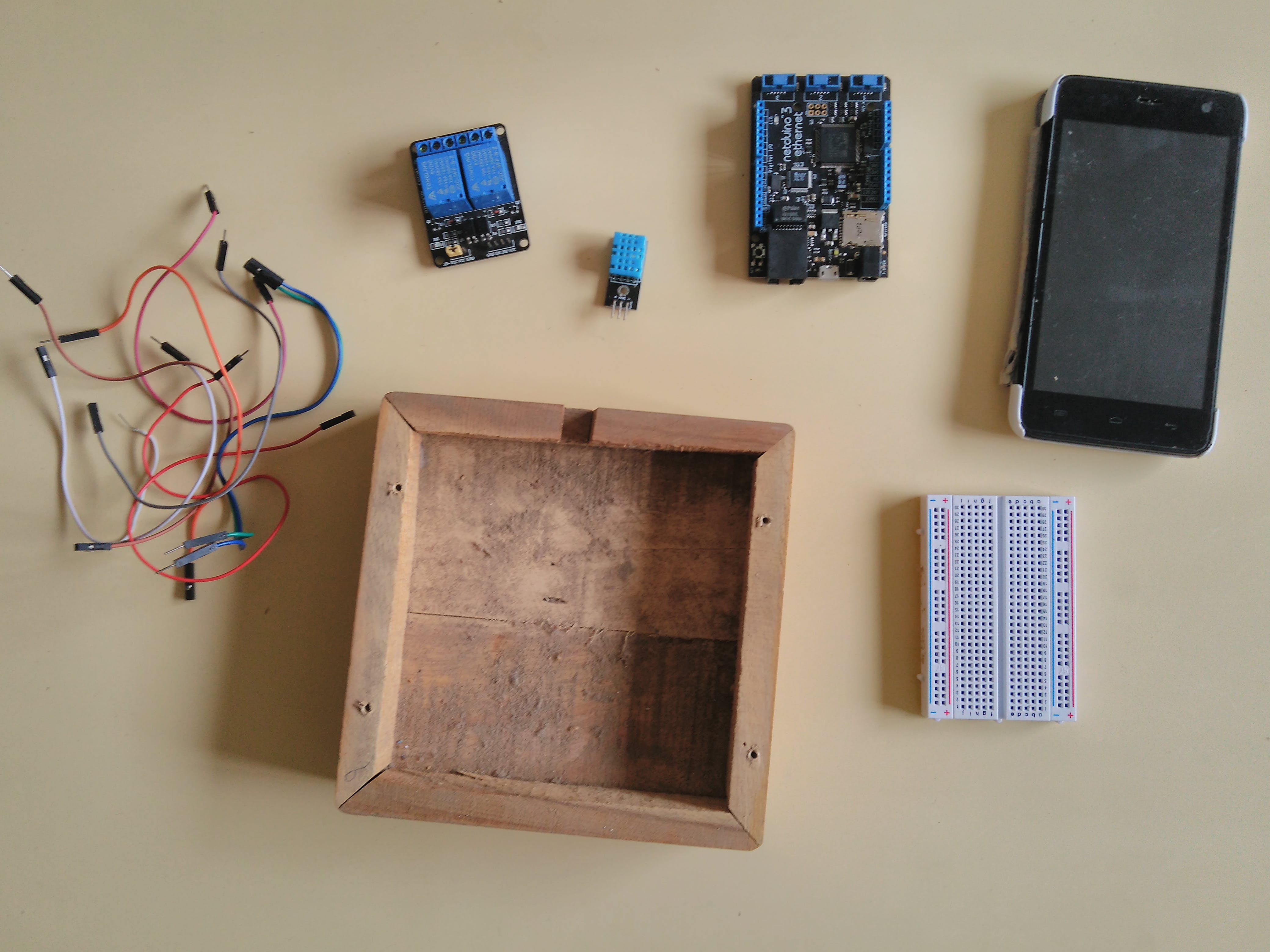
2.Netduino 设置
Netduino 是一款开发板,可让您使用 C# 编写代码来创建 IoT 应用程序。它使用 .NET 微框架。它就像一个 Arduino,具有许多令人兴奋的附加功能,例如 -
- 使用 WiFi 或以太网连接
- SD 卡支持额外的持久存储(高达 2GB)。
- 多得多.....
因此,要使用 Netduino,您将需要 Visual Studio 2015,它可以让您创建 .NET Micro Framework 应用程序。(请注意,仍然不支持 Visual Studio 2017)
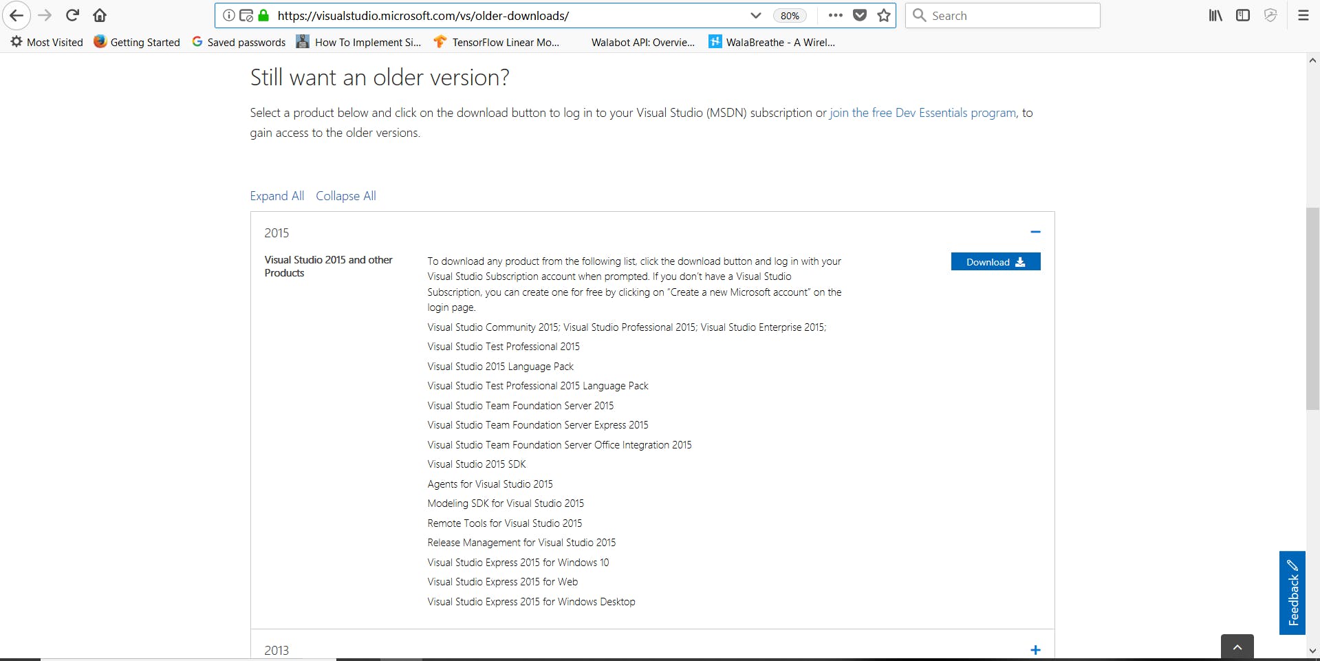
继续从上面的链接下载 VS 2015 的社区版本。
现在,在您安装后,请按照以下说明进行操作 -
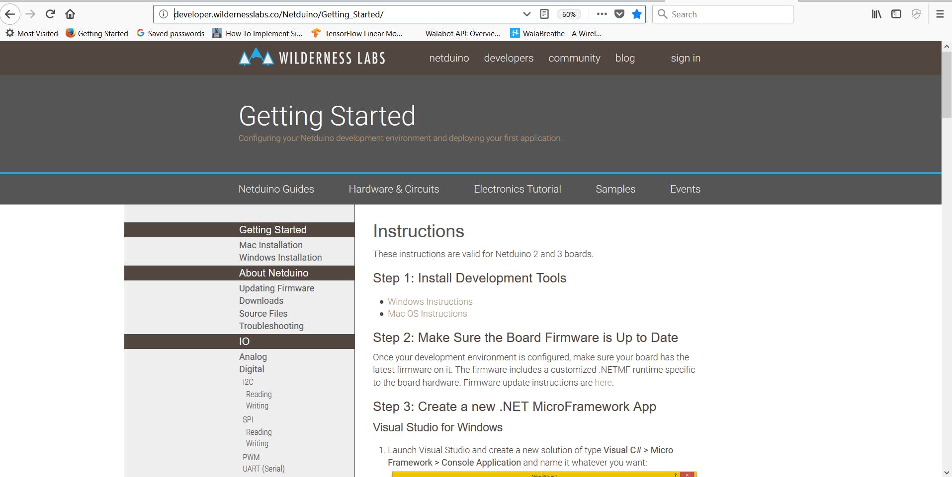
设置此设备有些困难,因此我建议您加入其社区,该社区非常活跃且乐于助人。我使用了 N3 以太网,所以我不需要 Netduino 部署设置部分。但是由于提供的软件,设置起来很容易。
3. 接线连接
现在您已经完成了所有设置,请转到 Netduino Samples repo 并下载 Blink 程序,然后使用 VS2015 在您的 Netduino 上运行它以确保一切正常。
https://github.com/WildernessLabs/Netduino_Samples
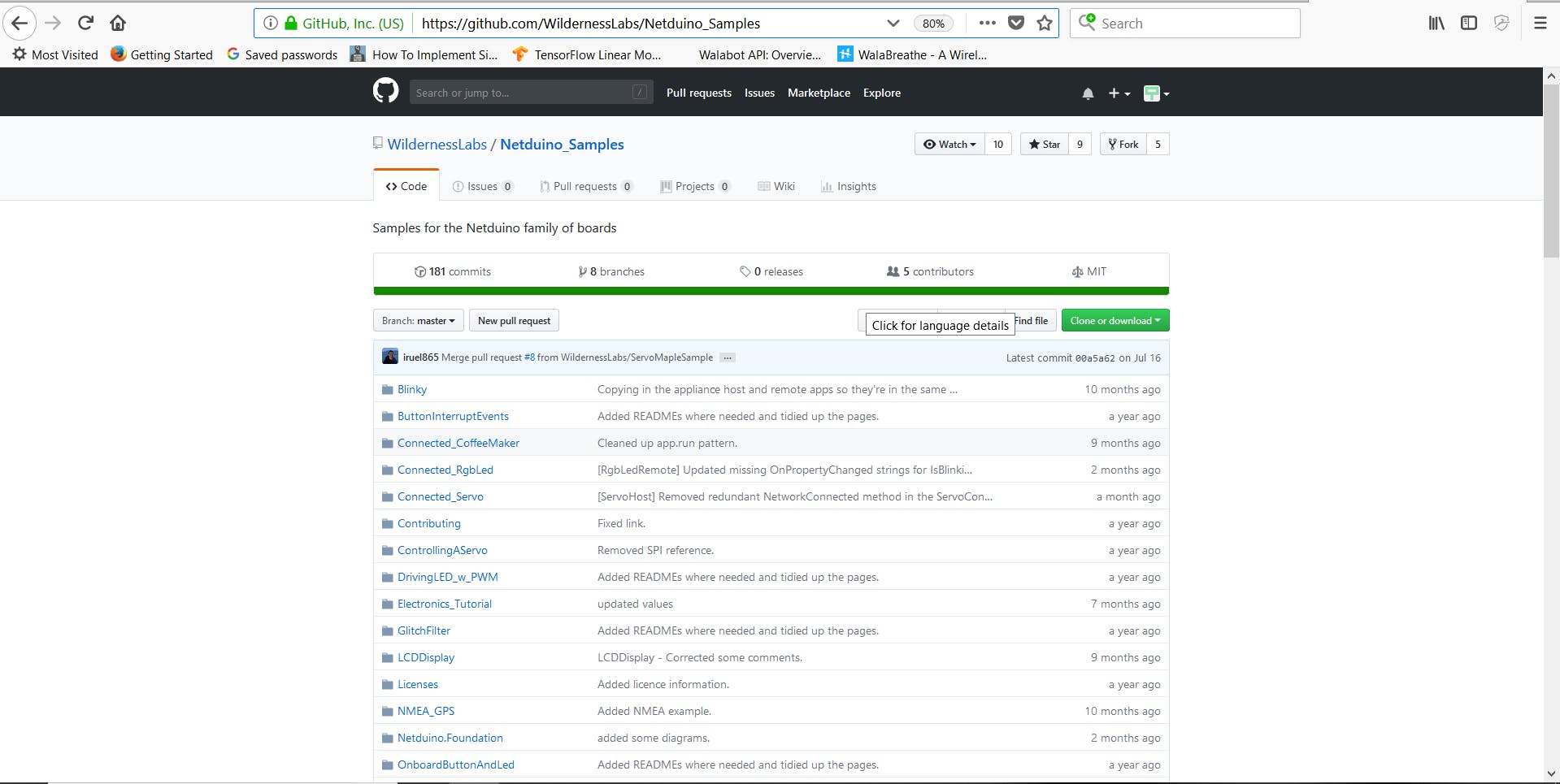
关注此视频以获得更多帮助。
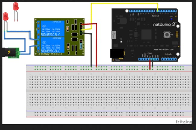
在此之后,您将设置为我们的项目连接连接。按照下图进行连接。
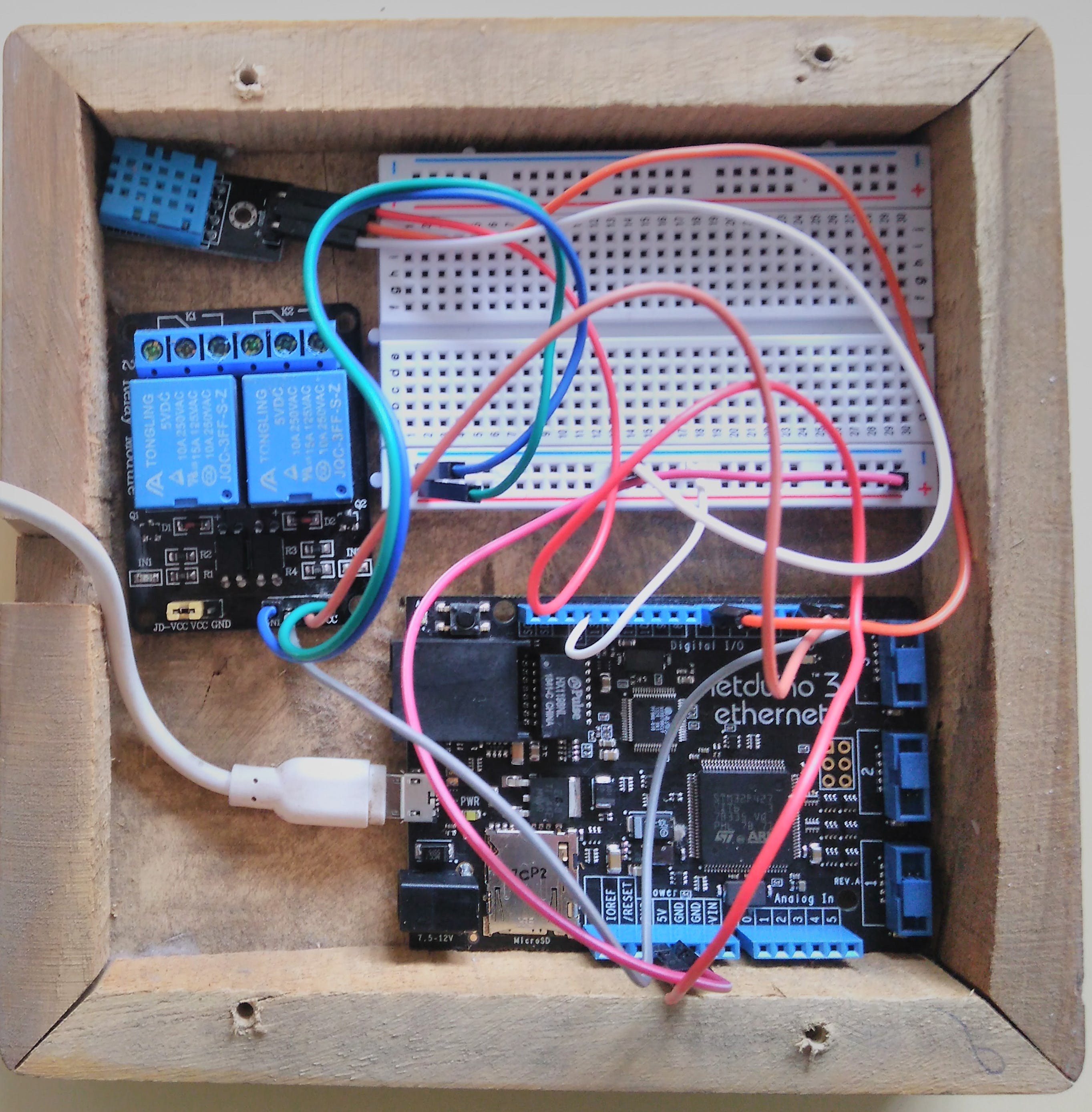
看看 Fritzing 的连接。
DHT11 的连接非常简单。
3.3V -传感器的 VCC
Gnd -传感器的 Gnd
数字引脚 2 -传感器的输出引脚
完成后,您就可以开始为您的项目编写代码了。
4. Netduino 的编码部分
现在,您的硬件已连接好,您已准备好对 Netduino 进行编码。我们将使用Netduino Samples Git repo 项目中提供的Request Handler和MapleServer Generation文件。将这些文件添加到您的 VS 项目中非常容易。此外,对于中继编码,我们将使用 Git 存储库的中继示例或连接的咖啡机示例。下面提供了指向我的 Git 存储库和 Netduino Samples Git 存储库的链接。
现在,要配置 DHT11 传感器,首先您需要 4 端子原始传感器,因为我使用的库只有在所有 4 个引脚都正确连接到电路板时才会运行。
using System;
using Microsoft.SPOT;
using Microsoft.SPOT.Hardware;
namespace Glovebox.Netduino.Drivers {
   public class DHT11 : DhtSensor{
       //private OutputPort m_op;
       //private OneWire m_ow;
       private OneWireBus.Device m_dev;
       public DHT11(Cpu.Pin data1, Cpu.Pin data2):base(data1,data2,Port.ResistorMode.Disabled)
       {
        //   m_op = new OutputPort(pin, false);
       }
       public float ConvertAndReadTemperature() {
           var data = 0L;
           // if reset finds no devices, just return 0
           if (m_ow.TouchReset() == 0)
               return 0;
           // address the device
           m_ow.WriteByte(Command.MatchROM);
           WriteBytes(m_dev.Address);
           // tell the device to start temp conversion
           m_ow.WriteByte(Command.StartTemperatureConversion);
           // wait for as long as it takes to do the temp conversion,
           // data sheet says ~750ms
           while (m_ow.ReadByte() == 0)
               System.Threading.Util.Delay(1);
           // reset the bus
           m_ow.TouchReset();
           // address the device
           m_ow.WriteByte(Command.MatchROM);
           WriteBytes(m_dev.Address);
           // read the data from the sensor
           m_ow.WriteByte(Command.ReadScratchPad);
           // read the two bytes of data
           data = m_ow.ReadByte(); // LSB
           data |= (ushort)(m_ow.ReadByte() << 8); // MSB
           // reset the bus, we don't want more data than that
           m_ow.TouchReset();
           // returns C
           // F would be:  (float)((1.80 * (data / 16.00)) + 32.00);
           return (float)data / 16f;
       }
       public void StartConversion() {
           // if reset finds no devices, just return 0
           if (m_ow.TouchReset() == 0)
               return;
           // address the device
           m_ow.WriteByte(Command.MatchROM);
           WriteBytes(m_dev.Address);
           // tell the device to start temp conversion
           m_ow.WriteByte(Command.StartTemperatureConversion);
       }
       public float ReadTemperature() {
           var data = 0L;
           // reset the bus
           m_ow.TouchReset();
           // address the device
           m_ow.WriteByte(Command.MatchROM);
           WriteBytes(m_dev.Address);
           // read the data from the sensor
           m_ow.WriteByte(Command.ReadScratchPad);
           // read the two bytes of data
           data = m_ow.ReadByte(); // LSB
           data |= (ushort)(m_ow.ReadByte() << 8); // MSB
           // reset the bus, we don't want more data than that
           m_ow.TouchReset();
           // returns C
           // F would be:  (float)((1.80 * (data / 16.00)) + 32.00);
           return (float)data / 16f;
       }
       public static float ToFahrenheit(float tempC) {
           return (9f / 5f) * tempC + 32f;
       }
       private void WriteBytes(byte[] data) {
           for (var i = 0; i < data.Length; i++)
               m_ow.WriteByte(data[i]);
       }
       private static class Command {
           public const byte SearchROM = 0xF0;
           public const byte ReadROM = 0x33;
           public const byte MatchROM = 0x55;
           public const byte SkipROM = 0xCC;
           public const byte AlarmSearch = 0xEC;
           public const byte StartTemperatureConversion = 0x44;
           public const byte ReadScratchPad = 0xBE;
           public const byte WriteScratchPad = 0x4E;
           public const byte CopySratchPad = 0x48;
           public const byte RecallEEPROM = 0xB8;
           public const byte ReadPowerSupply = 0xB4;
       }
   }
}
这是我要使用的库的代码。只需通过“使用”命令将其添加到 DHT11 显示文件中,然后将 D5 引脚配置为输出并在调试窗口上打印其状态。而已!
这是中继代码:
using System;
using Microsoft.SPOT;
using Microsoft.SPOT.Hardware;
using SecretLabs.NETMF.Hardware.Netduino;
using System.Threading;
namespace Relay
{
   public class Program
   {
       public static void Main()
       {
           // create an output port (a port that can be written to) and connect it to Digital Pin 2
           OutputPort relay = new OutputPort(Pins.GPIO_PIN_D2, false);
           OutputPort relay = new OutputPort(Pins.GPIO_PIN_D3, false);
           // run forever
           while (true)
           {
               relay.Write(true); // turn on the LED
               Thread.Sleep(500); // sleep for 1/2 second
               relay.Write(false); // turn off the relay
               Thread.Sleep(500); // sleep for 1/2 second
           }
       }
   }
}
让我们通过创建一个 Xamarin 应用程序来控制它,从而使开发板变得智能。
5. Xamarin 应用程序部分
现在我们已经准备好这些东西,我们将创建一个简单的 Xamarin 应用程序,该应用程序显示开关的状态(打开或关闭),并有 2 个按钮可以将开关的状态从关闭更改为打开。
以下是 2 个代码片段,可帮助您更多地了解上述功能。
获取状态代码片段:
public async Task<bool> GetLightSwitchStatus()
{
    using (var s = new Sockets.Plugin.TcpSocketClient())
    {
        await s.ConnectAsync(NetduinoIp, Port);
        byte[] data = new byte[2];
        data[0] = ReadLightSwitchState;
        data[1] = ReadLightSwitchState;
        s.WriteStream.Write(data, 0, 2);
        s.ReadStream.Read(data, 0, 1);
        return data[0] == ByteTrue;
    }
}
上面这段代码向服务器请求开关状态,并根据灯开关的状态返回真或假。
设置状态代码片段:
public async Task SetLightSwitchStatus(bool on)
{
    using (var s = new Sockets.Plugin.TcpSocketClient())
    {
        await s.ConnectAsync(NetduinoIp, Port);
        byte[] data = new byte[2];
        data[0] = WriteLightSwitchState;
        data[1] = (byte)(on ? ByteTrue : ByteFalse);
        s.WriteStream.Write(data, 0, 2);
    }
}
这段代码向服务器发送一个请求,告诉服务器应该将电灯开关设置为哪个状态。
请注意所有信息交换是如何通过字节完成的,第一个字节告诉服务器请求哪个操作,而第二个字节在必要时包含数据。
我已经使用 cssharpguy 的教程来创建我的简单应用程序。这是视频教程。
我遵循了连接的 CoffeeMaker 教程,并为该项目使用了相同的应用程序。
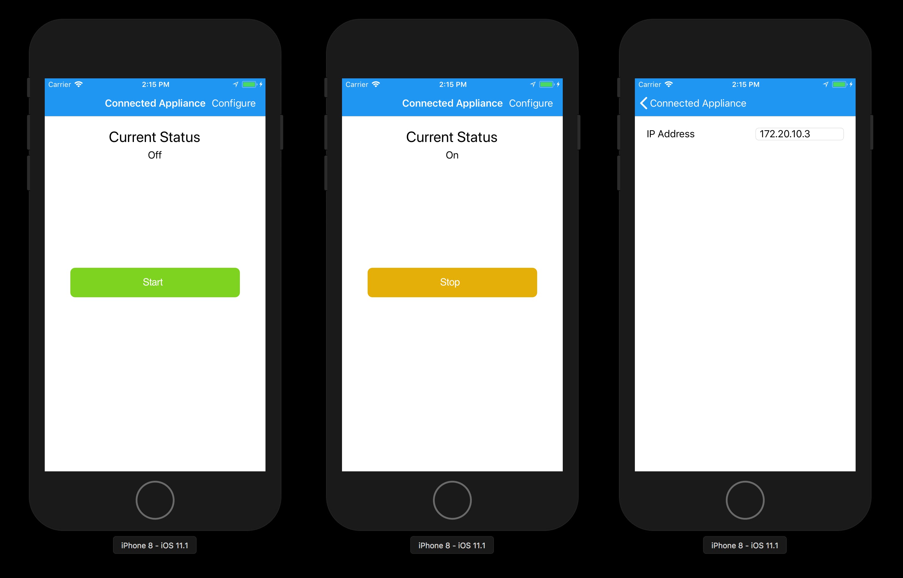
现在一切都完成了,该项目已准备好运行。这是显示项目工作的视频教程。
该视频是我以前的项目之一,但工作原理是相同的。我无法获得 Netduino 教程视频,因为我的 Netduino 板目前遇到一些问题,我的板开始工作后将立即更新视频。
感谢大家阅读这个项目。请尊重并与您的朋友分享。:-)
声明:本文内容及配图由入驻作者撰写或者入驻合作网站授权转载。文章观点仅代表作者本人,不代表电子发烧友网立场。文章及其配图仅供工程师学习之用,如有内容侵权或者其他违规问题,请联系本站处理。 举报投诉
- 相关下载
- 相关文章


