
资料下载


如何使用Arduino IDE编程ESP8266-12E
山中老虎
分享资料个
描述
大家好,今天我将讨论 Esp 物联网模块的功能并使用 Arduino IDE 对该模块进行编程。通常,USB 转 TTL 程序员可以完美地完成这项工作,但为了简单起见,我们使用 NodeMcu。
Esp8266-12E是一款基于 Wi-fi 的微控制器。这是我第一个使用这种类型的微控制器的项目,刚刚开始。
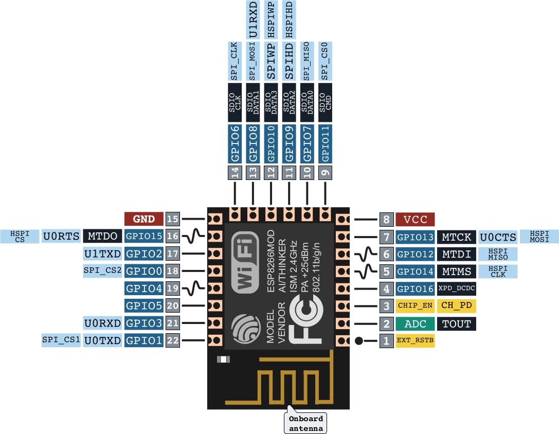
以下是一些规格:
1) 32位单片机
2)10位ADC(模数转换器)
3) 7- GPIO (输入/输出)
4) 无线网络 2.4Ghz
5)工作电压:3v至3.7v
6) 工作电流:80mA
7) 支持深度睡眠和待机功能
8) 网络协议:IPv4/HTTP/FTP
所以,这个微控制器比 Arduino 的 Atmega328p 好得多,但是 Arduino 很简单,并且有更多的 I/O 引脚。此外,Arduino 可以通过其开源 IDE 轻松编程。
对 ESP8266 进行编程:
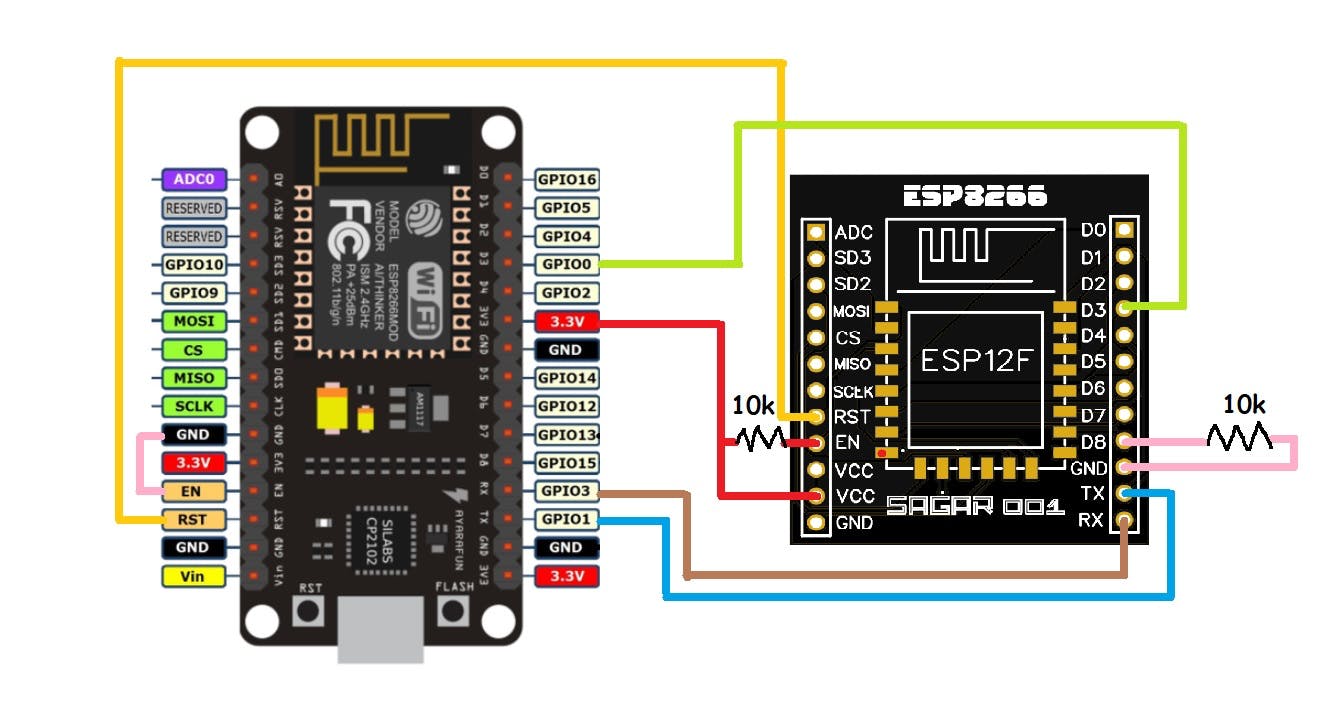
首先,我们要将此模块与其他MCU连接(支持USB转TTL功能),这里我们使用Nodemcu。我们的 Nodemcu 有 ch340g USB 转 TTL 编程器。使用下面给出的示意图进行所有连接。
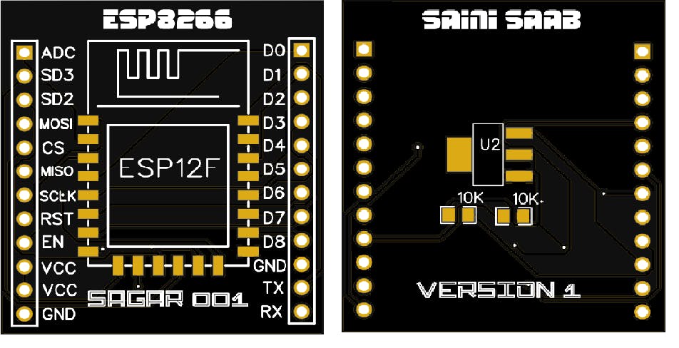
电路原理图:
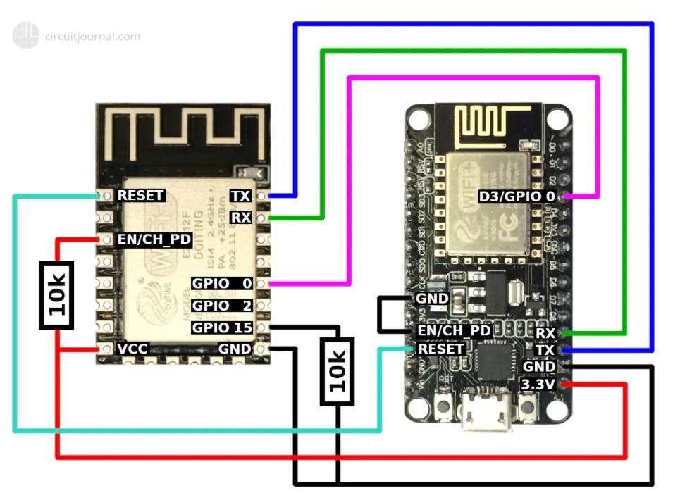
电路说明:
1) 使用 10k 电阻使 EN(使能)引脚高连接使能引脚到 VCC。
2) 将 GPIO-15 引脚设为低电平(使用 10k 电阻将其连接到 GND。
3) 将 TX 连接到 TX,将 RX 连接到 RX。
4)将Reset引脚连接到Nodemcu的Reset
5)使Nodemcu启用引脚低-直接将其连接到GND。
6) 将两者的 GPIO0/D3 相互连接。
7) 在两个模块中连接 GND 和 VCC。
ESP屏蔽:
Esp8266 模块不是面包板友好的,所以我设计了一个屏蔽来编程和操作这个微控制器。该屏蔽具有板载 3.3 伏稳压器和 10k 上拉/下拉电阻器。只需使用这个新原理图连接并直接上传代码。
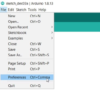
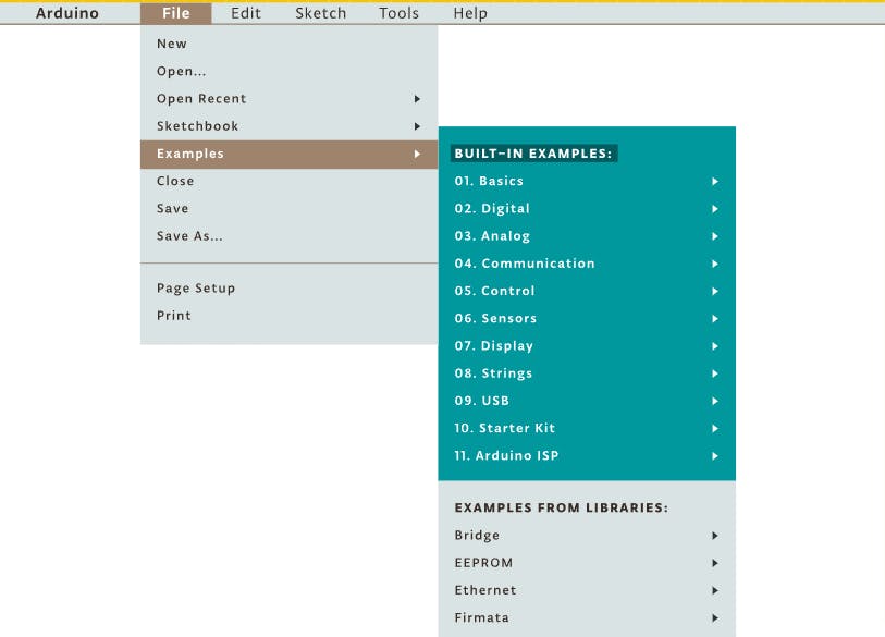
在 ESP 中上传代码:
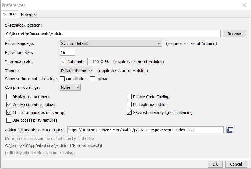
第 1 步:转到文件菜单下的首选项部分并粘贴此链接。
https://arduino.esp8266.com/stable/package_esp8266com_index.json
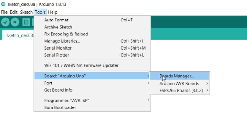
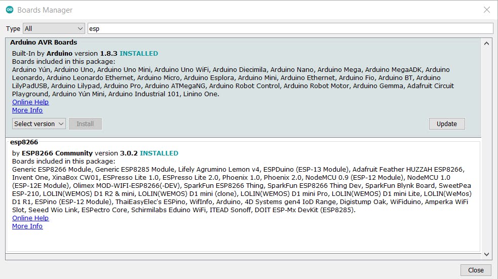
Step2:在工具部分选择板管理器和下载ESP板文件。
。
Step4:编译并上传代码。
Step5: 移除所有连接,您的 Esp8266 就可以使用了。
在这里,我将这个盾牌与 RGB neopixel 7 段 RGB 面板一起使用。这与此工作得很好。
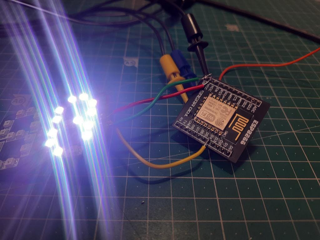
请参阅如何使用 ESP8266 制作 RGB 7 段时钟。
PCB和设计:
JLCPCB是最受欢迎的PCB制造商之一。2、4 和 6 层 PCB 的价格仅为 2 美元。他们刚刚以非常低的成本推出了新的紫色阻焊层、铝板和 3d 打印服务。Pcb 质量不惜任何代价。立即从此处查看它们。 https://jlcpcb.com/IAT
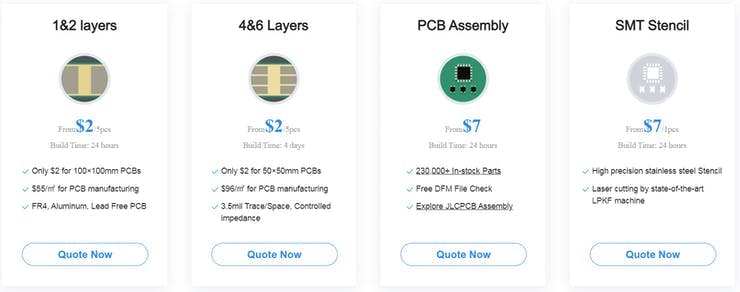
JLCPCB还提供SMT组装和SMT模板服务,不要忘记尝试这些服务。只需 7 美元即可试用PCB 组装。
测试代码:
1)闪烁:
void setup() {
  pinMode(LED_BUILTIN, OUTPUT);     // Initialize the LED_BUILTIN pin as an output
}

// the loop function runs over and over again forever
void loop() {
  digitalWrite(LED_BUILTIN, LOW);   // Turn the LED on (Note that LOW is the voltage level
  // but actually the LED is on; this is because
  // it is active low on the ESP-01)
  delay(1000);                      // Wait for a second
  digitalWrite(LED_BUILTIN, HIGH);  // Turn the LED off by making the voltage HIGH
  delay(2000);                      // Wait for two seconds (to demonstrate the active low LED)
}
2)超时:
#include

void ledOn() {
  digitalWrite(LED_BUILTIN, LOW);   // Turn the LED on (Note that LOW is the voltage level
}

void ledOff() {
  digitalWrite(LED_BUILTIN, HIGH);  // Turn the LED off by making the voltage HIGH
}

void ledToggle() {
  digitalWrite(LED_BUILTIN, !digitalRead(LED_BUILTIN));  // Change the state of the LED
}


esp8266::polledTimeout::periodicFastUs halfPeriod(500000); //use fully qualified type and avoid importing all ::esp8266 namespace to the global namespace

// the setup function runs only once at start
void setup() {
  Serial.begin(115200);

  Serial.println();
  Serial.printf("periodic/oneShotMs::timeMax()     = %u ms\n", (uint32_t)esp8266::polledTimeout::periodicMs::timeMax());
  Serial.printf("periodic/oneShotFastMs::timeMax() = %u ms\n", (uint32_t)esp8266::polledTimeout::periodicFastMs::timeMax());
  Serial.printf("periodic/oneShotFastUs::timeMax() = %u us\n", (uint32_t)esp8266::polledTimeout::periodicFastUs::timeMax());
  Serial.printf("periodic/oneShotFastNs::timeMax() = %u ns\n", (uint32_t)esp8266::polledTimeout::periodicFastNs::timeMax());

#if 0 // 1 for debugging polledTimeout
  Serial.printf("periodic/oneShotMs::rangeCompensate     = %u\n", (uint32_t)esp8266::polledTimeout::periodicMs::rangeCompensate);
  Serial.printf("periodic/oneShotFastMs::rangeCompensate = %u\n", (uint32_t)esp8266::polledTimeout::periodicFastMs::rangeCompensate);
  Serial.printf("periodic/oneShotFastUs::rangeCompensate = %u\n", (uint32_t)esp8266::polledTimeout::periodicFastUs::rangeCompensate);
  Serial.printf("periodic/oneShotFastNs::rangeCompensate = %u\n", (uint32_t)esp8266::polledTimeout::periodicFastNs::rangeCompensate);
#endif

  pinMode(LED_BUILTIN, OUTPUT);     // Initialize the LED_BUILTIN pin as an output

  using esp8266::polledTimeout::oneShotMs; //import the type to the local namespace

  //STEP1; turn the led ON
  ledOn();

  //STEP2: wait for ON timeout
  oneShotMs timeoutOn(2000);
  while (!timeoutOn) {
    yield();
  }

  //STEP3: turn the led OFF
  ledOff();

  //STEP4: wait for OFF timeout to assure the led is kept off for this time before exiting setup
  oneShotMs timeoutOff(2000);
  while (!timeoutOff) {
    yield();
  }

  //Done with STEPs, do other stuff
  halfPeriod.reset(); //halfPeriod is global, so it gets inited on sketch start. Clear it here to make it ready for loop, where it's actually used.
}


// the loop function runs over and over again forever
void loop() {
  if (halfPeriod) {
    ledToggle();
  }
}
3)无延迟闪烁:
int ledState = LOW;

unsigned long previousMillis = 0;
const long interval = 1000;

void setup() {
  pinMode(LED_BUILTIN, OUTPUT);
}

void loop() {
  unsigned long currentMillis = millis();
  if (currentMillis - previousMillis >= interval) {
    previousMillis = currentMillis;
    if (ledState == LOW) {
      ledState = HIGH;  // Note that this switches the LED *off*
    } else {
      ledState = LOW;  // Note that this switches the LED *on*
    }
    digitalWrite(LED_BUILTIN, ledState);
  }
}
在此板的示例部分中查找更多程序。
更多项目:
2)使用 JLCPCB SMT 组装服务的 8x8 Neopixel RGB 矩阵。
认为您喜欢我的工作,请继续关注。在 Instagram (sagar_saini_7294) 和 hackaday 上关注我们。
声明:本文内容及配图由入驻作者撰写或者入驻合作网站授权转载。文章观点仅代表作者本人,不代表电子发烧友网立场。文章及其配图仅供工程师学习之用,如有内容侵权或者其他违规问题,请联系本站处理。 举报投诉
- 相关下载
- 相关文章


