资料下载

直流/直流µ模块调节器印刷电路板设计指南
The LTM8020, LTM8021, LTM8022 and LTM8023 μModule® regulators are complete easy-to-use encapsulated stepdown DC/DC regulators intended to take the pain and aggravation out of implementing a switching power supply onto a system board. With a μModule regulator, you only need an input cap, output cap and one or two resistors to complete the design. As one might imagine, this high level of integration greatly simplifi es the task of printed circuit board design, reducing the effort to four categories: component footprint generation, component placement, routing the nets, and thermal vias.
Component Footprint Generation One of the fi rst things to do when designing a printed circuit board is generate the footprint or decal for each component. The components required to complete the LTM8020, LTM8021, LTM8022 and LTM8023 designs are common resistors and capacitors that have industry standard footprints. The basic information necessary to generate the footprint for a LTM8020, LTM8021, LTM8022 or LTM8023 is given in the package outline drawing, which can be found in the “Package Description” section of the data sheet, which is also accessible online at:
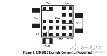
Component Placement In general, components should be placed in a manner which results in traces that are as short as possible. There are very few components to put down so component placement is simple. For example, on the LTM8020, the typical components are the μModule regulator, a single output voltage resistor, along with an input and output cap. In order to keep the traces as short as possible, place the set resistor RADJ adjacent to the ADJ pad, the input cap CIN next to VIN and the output cap COUT next to VOUT. An example of this is shown in Figure 1.

声明:本文内容及配图由入驻作者撰写或者入驻合作网站授权转载。文章观点仅代表作者本人,不代表电子发烧友网立场。文章及其配图仅供工程师学习之用,如有内容侵权或者其他违规问题,请联系本站处理。 举报投诉
- 相关下载
- 相关文章


