
资料下载


128RFA1低功耗是如何实现的
分享资料个
Features
• High Performance, Low Power AVR® 8-Bit Microcontroller
• Advanced RISC Architecture
- 135 Powerful Instructions – Most Single Clock Cycle Execution
- 32x8 General Purpose Working Registers
- Fully Static Operation
- Up to 16 MIPS Throughput at 16 MHz and 1.8V
- On-Chip 2-cycle Multiplier
• Non-volatile Program and Data Memories
- 128K Bytes of In-System Self-Programmable Flash
• Endurance: 10’000 Write/Erase Cycles @ 125°C (25’000 Cycles @ 85°C)
- 4K Bytes EEPROM
• Endurance: 20’000 Write/Erase Cycles @ 125°C (100’000 Cycles @ 25°C)
- 16K Bytes Internal SRAM
• JTAG (IEEE std. 1149.1 compliant) Interface
- Boundary-scan Capabilities According to the JTAG Standard
- Extensive On-chip Debug Support
- Programming of Flash EEPROM, Fuses and Lock Bits through the JTAG interface
• Peripheral Features
- Multiple Timer/Counter & PWM channels
- Real Time Counter with Separate Oscillator
- 10-bit, 330 ks/s A/D Converter; Analog Comparator; On-chip Temperature Sensor
- Master/Slave SPI Serial Interface
- Two Programmable Serial USART
- Byte Oriented 2-wire Serial Interface
• Advanced Interrupt Handler
• Watchdog Timer with Separate On-Chip Oscillator
• Power-on Reset and Low Current Brown-Out Detector
• Advanced Power Save Modes
• Fully integrated Low Power Transceiver for 2.4 GHz ISM Band
- Supported Data Rates: 250 kb/s and 500 kb/s, 1 Mb/s, 2 Mb/s
- -100 dBm RX Sensitivity; TX Output Power up to 3.5 dBm
- Hardware Assisted MAC (Auto-Acknowledge, Auto-Retry)
- 32 Bit IEEE 802.15.4 Symbol Counter
- Baseband Signal Processing
- SFD-Detection, Spreading; De-Spreading; Framing ; CRC-16 Computation
- Antenna Diversity and TX/RX control
- TX/RX 128 Byte Frame Buffer
• Hardware Security (AES, True Random Generator)
• Integrated Crystal Oscillators (32.768 kHz & 16 MHz, external crystal needed)
• I/O and Package
- 38 Programmable I/O Lines
- 64-pad QFN (RoHS/Fully Green)
• Temperature Range: -40°C to 125°C Industrial
• Supply voltage range 1.8V to 3.6V with integrated voltage regulators
• Ultra Low Power consumption (1.8 to 3.6V) for Rx/Tx & AVR: 《18.6 mA
- CPU Active Mode (16MHz): 4 .1 mA
- 2.4GHz Transceiver: RX_ON 12.5 mA / TX 14.5 mA (maximum TX output power)
- Deep Sleep Mode: 《250nA @ 25°C
• Speed Grade: 0 – 16 MHz @ 1.8 – 3.6V
Applications
• ZigBee® / IEEE 802.15.4-2006/2003™ – Full And Reduced Function Device (FFD/RFD)
• General Purpose 2.4GHz ISM Band Transceiver with Microcontroller
• RF4CE, SP100, WirelessHART™, ISM Applications and IPv6 / 6LoWPAN
8-bit Microcontroller with Low Power 2.4GHz Transceiver for ZigBee and IEEE 802.15.4
ATmega128RFA1
PRELIMINARY
8266FS-MCU Wireless-09/14
1
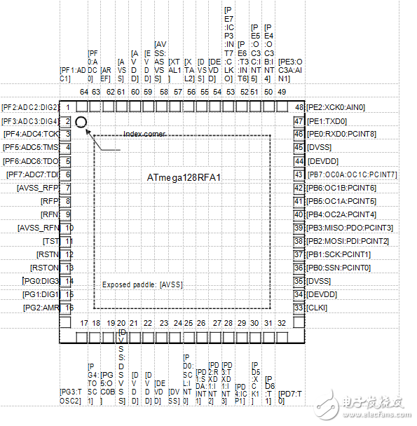
1 Pin Configurations
Figure 1-1. Pinout ATmega128RFA1
[PF1:ADC1][PF0:ADC0][AREF][AVSS][AVDD][EVDD][AVSS:ASVSS][XTAL1][XTAL2][DVSS][DEVDD][PE7:ICP3:INT7:CLKO][PE6:T3:INT6][PE5:OC3C:INT5][PE4:OC3B:INT4][PE3:OC3A:AIN1]
64636261605958575655545352515049
[PF2:ADC2:DIG2]1 48[PE2:XCK0:AIN0]
[PF3:ADC3:DIG4]2 47 [PE1:TXD0]
[PF4:ADC4:TCK]3 Index corner 46 [PE0:RXD0:PCINT8]
[PF5:ADC5:TMS]4 45 [DVSS]
[PF6:ADC6:TDO]5 44 [DEVDD]
[PF7:ADC7:TDI]6 ATmega128RFA1 43 [PB7:OC0A:OC1C:PCINT7]
[AVSS_RFP]7 42[PB6:OC1B:PCINT6]
[RFP]8 41[PB5:OC1A:PCINT5]
[RFN]9 40[PB4:OC2A:PCINT4]
[AVSS_RFN] 10 39[PB3:MISO:PDO:PCINT3]
[TST] 11 38[PB2:MOSI:PDI:PCINT2]
[RSTN] 12 37[PB1:SCK:PCINT1]
[RSTON] 13 36[PB0:SSN:PCINT0]
[PG0:DIG3] 14 Exposed paddle: [AVSS] 35[DVSS]
[PG1:DIG1] 15 34[DEVDD]
[PG2:AMR] 16 33[CLKI]
17181920212223242526272829303132
[PG3:TOSC2][PG4:TOSC1][PG5:OC0B][DVSS:DSVSS][DVDD][DVDD][DEVDD][DVSS][PD0:SCL:INT0][PD1:SDA:INT1][PD2:RXD1:INT2][PD3:TXD1:INT3][PD4:ICP1][PD5:XCK1][PD6:T1][PD7:T0]
Note: The large center pad underneath the QFN/MLF package is made of metal and internally connected to AVSS. It should be soldered or glued to the board to ensure good mechanical stability. If the center pad is left unconnected, the package might loosen from the board. It is not recommended to use the exposed paddle as a replacement of the regular AVSS pins.
2 Disclaimer
Typical values contained in this datasheet are based on simulation and characterization results of other AVR microcontrollers and radio transceivers manufactured in a similar process technology. Minimum and Maximum values will be available after the device is characterized.
声明:本文内容及配图由入驻作者撰写或者入驻合作网站授权转载。文章观点仅代表作者本人,不代表电子发烧友网立场。文章及其配图仅供工程师学习之用,如有内容侵权或者其他违规问题,请联系本站处理。 举报投诉
- 相关下载
- 相关文章


