
资料下载


Bit Duino一体式机器人防护罩
李泽坚
分享资料个
PCB图如下: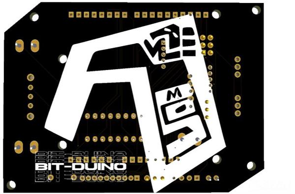
成分
| 针排接头公 - 母 1x40 2.54mm | × 1 |
| 公排针 | × 2 |
| L293d驱动IC | × 1 |
| DIP 插座 28/16 针 | × 1 |
| 2Pin 螺丝端子 5mm 间距 | × 3 |
|
电阻封装 PCBway |
× 1 |
|
开关套件通孔 PCBway |
× 1 |
|
LED 套件。 PCBway |
× 1 |
|
单刀双掷 DIYhz商店 |
× 1 |
描述
Bit-Duino 一体式机器人防护罩
这个 Arduino Uno 开发板是为初学者设计的,他们可以尝试使用参考代码进行自我编程。他们可以轻松地使用参考代码并创建他们的项目!使用它,您可以控制两个电机和两个伺服电机。你的想象力是你唯一的限制!使用它,您可以学习如何使用一些传感器,并且可以从头开始创建自己的项目!
如何给盾牌加电。
您可以使用任何类型的电池,这是您的选择。确保它们位于电池外壳中,并且有两根电线分别为负极和正极。螺钉端子在这里用作连接器。
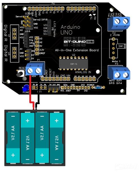
工作电压 - 7 至 9V
连接传感器和模块。
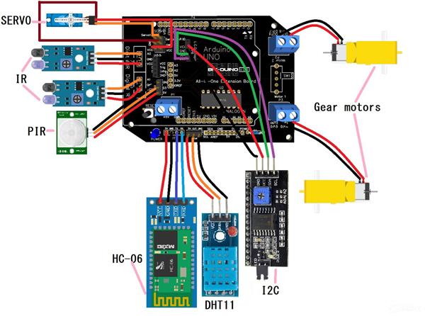
让我们了解每个组件以及它们的用途,
L293D IC - 用于控制两个电机。
LED -作为电源指示灯。
1k 电阻- 降低 LED 的电压和电流
公针头 -要将屏蔽连接到 Arduino,连接伺服电机,并连接传感器。
母针头- 连接传感器,连接额外的针脚。
SPDT 开关- 打开/关闭屏蔽。
按钮 -重置代码。
螺丝端子- 连接电源线,连接输出电机线。
参考代码'
代码随#define 和伺服库一起提供。
#include#define motor1 4 #define motor2 5 #define motor3 6 #define motor4 7 伺服.servo1; 伺服.servo2; #define tx 0 #define rx 1 #define trig 2 #define echo 8 #define pir_out 3 #define temp 11 #define ir1 A0 #define ir2 A1 #define sda A4 #define scl A5 void setup () { //把你的设置代码在这里,运行一次: servo1.attach( 9 ); 伺服2.attach(10); } void loop () { // 把你的主要代码放在这里,重复运行: }
如果您想控制伺服电机,请将其放入格式和每个程序中。
#include <伺服.h>
伺服.servo1;
伺服.servo2;
void  setup ()  {
  // 把你的设置代码放在这里,运行一次:
 servo1.attach( 9 );
 伺服2.attach(10);

}

void  loop ()  {
  // 把你的主要代码放在这里,重复运行:

}
电机控制代码。
#define motor1 4
#define motor2 5
#define motor3 6
#define motor4 7
#define tx 0
#define rx 1
#define trig 2
#define echo 8
#define pir_out 3
#define temp 11
#define ir1 A0
#define ir2 A1
#define sda A4
#define scl A5
void  setup ()  {
  // 把你的设置代码放在这里,运行一次:
pinMode(电机1,输出)
pinMode(电机2,输出)
pinMode(电机3,输出)
pinMode(motor4,OUTPUT)//告诉arduino电机引脚是输出/它们是控制引脚。
}

void  loop ()  {
  // 把你的主要代码放在这里,重复运行:
 //1st motor forward/backward code
数字写入(电机1,高)
digitalWrite(motor2,LOW)//沿一个方向运行第一个电机(将电机连接到螺钉端子并查看它的旋转位置,如果向前旋转则向前旋转,如果向后旋转则向后旋转)

数字写入(电机 1,低)
digitalWrite(motor2,HIGH)//根据上面的代码以相反的方向运行第一个电机。
//

//第二个电机前进/后退代码
数字写入(电机 3,高)
digitalWrite(motor4,LOW)//沿一个方向运行第二个电机(将电机连接到螺钉端子并查看它的旋转位置,如果向前旋转则向前旋转,如果向后旋转则向后旋转)

数字写入(电机 3,低)
digitalWrite(motor4,HIGH)//根据上面的代码以相反的方向运行第二个电机。
//

//第一个电机停止代码
数字写入(电机 1,低)
digitalWrite(motor2, LOW) //停止第一个电机。
//

//第二个电机停止代码
数字写入(电机 3,低)
digitalWrite(motor4, LOW) //停止第二个电机。
//

//要转弯,你应该让一个轮子停止和一个运行,然后记录它的转弯位置。然后你可以创建一个名为“turn *the side turn*”的函数并在你的项目中使用它。使功能向前(所有两个轮子都向前运行),向后(所有两个轮子都向后运行),停止(所有两个轮子都停止)并在您的项目中使用它们。
}
超声波距离传感器代码
#define motor1 4
#define motor2 5
#define motor3 6
#define motor4 7
#define tx 0
#define rx 1
#define trig 2
#define echo 8
#define pir_out 3
#define temp 11
#define ir1 A0
#define ir2 A1
#define sda A4
#define scl A5
void  setup ()  {
  // 把你的设置代码放在这里,运行一次:
pinMode(trig,OUTPUT); //设置引脚触发输出
pinMode(echo,INPUT); //设置pin echo到输入
}

void  loop ()  {
  // 把你的主要代码放在这里,重复运行:
 数字写入(触发,低);
 延迟微秒(2);
 数字写入(触发,高);
 延迟微秒(2);
 数字写入(触发,低);
长t = 脉冲输入(回声,高);// 启动传感器

长英寸 = t / 74 / 2 ;
长cm = t / 29 / 2 ; // 获取实际的 in/cm 值

if (cm< 10 ){
  //如果传感器检测到距离它不到 10cm 的物体*sensor*,则无论您在此处编写什么程序都会运行。可以将上面的“<”替换为任意符号,使其为“小于”、“等于”、“等于或小于”或“等于或大于”。
}

}
PIR 传感器代码
#define motor1 4
#define motor2 5
#define motor3 6
#define motor4 7
#define tx 0
#define rx 1
#define trig 2
#define echo 8
#define pir_out 3
#define temp 11
#define ir1 A0
#define ir2 A1
#define sda A4
#define scl A5
void  setup ()  {
  // 把你的设置代码放在这里,运行一次:
 pinMode(pir_out,输入);
}

void  loop ()  {
  // 把你的主要代码放在这里,重复运行:
int val = digitalRead(pir_out);

if (val == 1 ){
  //在这里放一个函数,当传感器检测到运动时它将运行。
}
if (val == 0 ){
  //在这里放一个函数,当传感器没有检测到任何运动时它就会运行。
}
}
HC-05/HC-06蓝牙模块代码(存收号)
字符;
#define motor1 4
#define motor2 5
#define motor3 6
#define motor4 7
#define tx 0
#define rx 1
#define trig 2
#define echo 8
#define pir_out 3
#define temp 11
#define ir1 A0
#define ir2 A1
#define sda A4
#define scl A5
void  setup () {
  // 把你的设置代码放在这里,运行一次:
Serial.begin( 9600 );
}

void  loop () {
  // 把你的主要代码放在这里,重复运行:
if (Serial.available()){
 ble = Serial.read();

}
if (ble == ' //你要通过蓝牙发送的任何数字' ){
  //当蓝牙模块检测到给定的数字时,你在这里编码的任何东西都会运行。仅支持数字,需要智能手机发送信号。您可以使用任何 android Arduino 蓝牙控制应用程序并使用下面的代码测试信号。请记住在上传代码时删除蓝牙模块并在上传完成后重新连接。否则代码不会上传,否则会严重损坏您的蓝牙模块。
}
}
要通过蓝牙存储和接收字符,请访问https://forum.arduino.cc/t/receiving-text-strings-over-bluetooth/232452
有关其他传感器代码,请访问https://forum.arduino.cc
如果您是 Arduino 编程的初学者,请访问https://www.arduino.cc/en/Guide/
始终使用“#define 和伺服库”。当你用这个构建一些东西时的代码。
我为什么做这个?
我这样做是因为当我还是初学者时,我很难使用其他类型的电机控制器。所以问题是,
做大项目时总是忘记别针。
很多将 Arduino 连接到传感器的电线非常混乱。
没有专用的传感器连接器。
没有内置开关,这总是意味着要在外部连接一个。
所以在这个板上,我已经消除了所有这些问题。
我可以用这个板做什么样的项目?
各种项目!喜欢
避障车
线跟车
运动感应自动皂液器等等!想象力是你唯一的限制!
需要注意的是,
焊接时,将 Arduino Uno 公针焊接在 PCB 下方,以便它们可以用作屏蔽。例如:-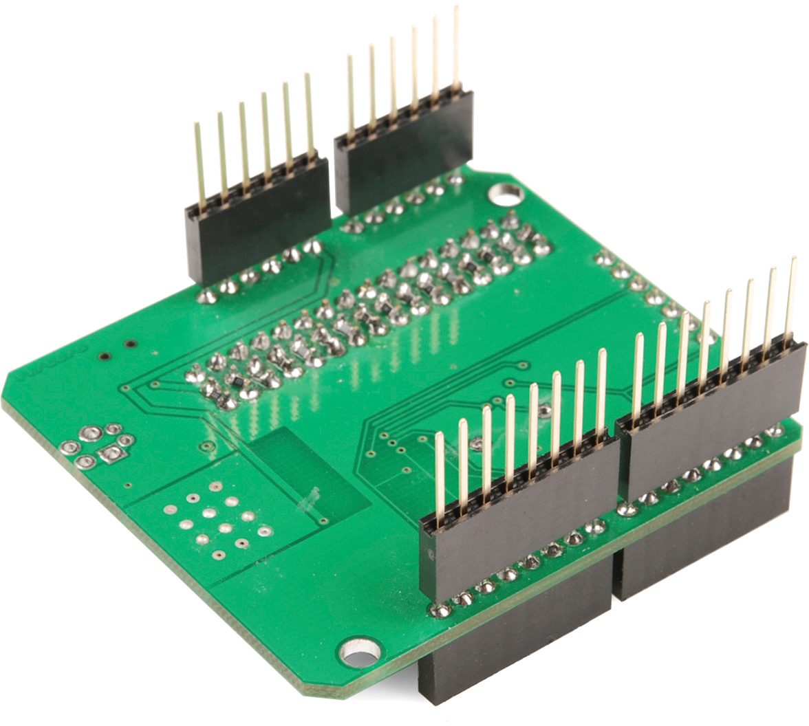
您应该知道如何对 Arduino Uno 进行编程(例如:制作一个函数)
您可以选择将传感器和模块引脚与母头/公头连接。
焊接元件后,剪掉多余的部分。
如果您想更换 IC,请使用 IC 插座底座
不得转载,仅用于您的工作。
DP 代表 DigitalPin
温度传感器输出 DP 为 11
TEMP代表温度传感器(DHT11模块)
UDS代表超声波距离传感器
BT1代表蓝牙模块(兼容HC-05、HC-06 4pin模块)
数字红外是一种红外传感器。
PIR 是被动红外传感器/运动传感器。
使用 LCD 显示模块时使用 I2C 转换器。
代码
位duino_define_and_servo_code
Bit-duino_define_and_servo_code.ino
C/C++
下载(3)
|
#include |
|
| #define motor1 4 | |
| #define motor2 5 | |
| #define motor3 6 | |
| #define motor4 7 | |
| Servo.servo1; | |
| Servo.servo2; | |
| #define tx 0 | |
| #define rx 1 | |
| #define trig 2 | |
| #define echo 8 | |
| #define pir_out 3 | |
| #define temp 11 | |
| #define ir1 A0 | |
| #define ir2 A1 | |
| #define sda A4 | |
| #define scl A5 | |
| void setup() { | |
| // put your setup code here, to run once: | |
| servo1.attach(9); | |
| servo2.attach(10); | |
| } | |
| void loop() { | |
| // put your main code here, to run repeatedly: | |
| } |
电机控制
C/C++
|
#include |
|
| #define motor1 4 | |
| #define motor2 5 | |
| #define motor3 6 | |
| #define motor4 7 | |
| Servo.servo1; | |
| Servo.servo2; | |
| #define tx 0 | |
| #define rx 1 | |
| #define trig 2 | |
| #define echo 8 | |
| #define pir_out 3 | |
| #define temp 11 | |
| #define ir1 A0 | |
| #define ir2 A1 | |
| #define sda A4 | |
| #define scl A5 | |
| void setup() { | |
| // put your setup code here, to run once: | |
| servo1.attach(9); | |
| servo2.attach(10); | |
| pinMode(motor1, OUTPUT) | |
| pinMode(motor2, OUTPUT) | |
| pinMode(motor3, OUTPUT) | |
| pinMode(motor4, OUTPUT)// telling arduino that the motor pins are output/they are the controlling pins. | |
| } | |
| void loop() { | |
| // put your main code here, to run repeatedly: | |
| //1st motor forward/backward code | |
| digitalWrite(motor1, HIGH) | |
| digitalWrite(motor2, LOW)// runs the 1st motor in a direction (connct the motor to the screw terminal and see where it is rotating, if rotating forward it is forward, if rotating backward it is backward) | |
| digitalWrite(motor1, LOW) | |
| digitalWrite(motor2, HIGH)// runs the 1st motor in the opposite direction according to the above piece of code. | |
| // | |
| //2nd motor forward/backward code | |
| digitalWrite(motor3, HIGH) | |
| digitalWrite(motor4, LOW)// runs the 2nd motor in a direction (connct the motor to the screw terminal and see where it is rotating, if rotating forward it is forward, if rotating backward it is backward) | |
| digitalWrite(motor3, LOW) | |
| digitalWrite(motor4, HIGH)// runs the 2nd motor in the opposite direction according to the above piece of code. | |
| // | |
| //1st motor stop code | |
| digitalWrite(motor1, LOW) | |
| digitalWrite(motor2, LOW)//stops the 1st motor. | |
| // | |
| //2nd motor stop code | |
| digitalWrite(motor3, LOW) | |
| digitalWrite(motor4, LOW)//stops the 2nd motor. | |
| // | |
| //to turn you should make one wheel stop and one running, and then record where its turning. then you can make a function called "turn *the side turned*" and use it on your project. make functions to forward(all two wheels running forward), backward (all two wheels running backward), stop( all two wheels stop) and use them on your project. | |
| } |
Ultrasonic_Distance_Sensor_code
C/C++
| #define motor1 4 | |
| #define motor2 5 | |
| #define motor3 6 | |
| #define motor4 7 | |
| #define tx 0 | |
| #define rx 1 | |
| #define trig 2 | |
| #define echo 8 | |
| #define pir_out 3 | |
| #define temp 11 | |
| #define ir1 A0 | |
| #define ir2 A1 | |
| #define sda A4 | |
| #define scl A5 | |
| void setup() { | |
| // put your setup code here, to run once: | |
| pinMode(trig,OUTPUT);//setting pin trig to output | |
| pinMode(echo,INPUT);//setting pin echo to input | |
| } | |
| void loop() { | |
| // put your main code here, to run repeatedly: | |
| digitalWrite(trig,LOW); | |
| delayMicroseconds(2); | |
| digitalWrite(trig,HIGH); | |
| delayMicroseconds(2); | |
| digitalWrite(trig,LOW); | |
| long t = pulseIn(echo, HIGH);// starting the sensor | |
| long inches = t / 74 / 2; | |
| long cm = t / 29 / 2; // getiing the real in/cm value | |
| if(cm<10){ | |
| //whatever you program here will run if the sensor detects something less than 10cm away from it*sensor*. can replace the above "<" with any symbol and make it "less than", "equal", "equal or less than" or "equal or greater than". | |
| } | |
| } |
PIR_sensor_code
C/C++
| #define motor1 4 | |
| #define motor2 5 | |
| #define motor3 6 | |
| #define motor4 7 | |
| #define tx 0 | |
| #define rx 1 | |
| #define trig 2 | |
| #define echo 8 | |
| #define pir_out 3 | |
| #define temp 11 | |
| #define ir1 A0 | |
| #define ir2 A1 | |
| #define sda A4 | |
| #define scl A5 | |
| void setup() { | |
| // put your setup code here, to run once: | |
| pinMode(pir_out, INPUT); | |
| } | |
| void loop() { | |
| // put your main code here, to run repeatedly: | |
| int val = digitalRead(pir_out); | |
| if (val == 1){ | |
| //put a function here and it will run when sensor detects motion. | |
| } | |
| if (val == 0){ | |
| //put a function here and it will run when sensor doesn't detect any motion. | |
| } | |
| } |
Bluetooth_HC-06_module_receiving_numbers_code
C/C++
| char ble; | |
| #define motor1 4 | |
| #define motor2 5 | |
| #define motor3 6 | |
| #define motor4 7 | |
| #define tx 0 | |
| #define rx 1 | |
| #define trig 2 | |
| #define echo 8 | |
| #define pir_out 3 | |
| #define temp 11 | |
| #define ir1 A0 | |
| #define ir2 A1 | |
| #define sda A4 | |
| #define scl A5 | |
| void setup() { | |
| // put your setup code here, to run once: | |
| Serial.begin(9600); | |
| } | |
| void loop() { | |
| // put your main code here, to run repeatedly: | |
| if(Serial.available()){ | |
| ble = Serial.read(); | |
| } | |
| if (ble == ' //any number you are going to send through bluetooth '){ | |
| //anything you code here gonna run when bluetooth module detects the given number. only numbers supported and requires smartphone to send signals. you can use any android Arduino Bluetooth control app and test the signal using the code below. remember when uploading the code remove the bluetooth module and reconnect it when the uploading is finished. or else the code is not gonna upload or it can severely damage your bluetooth module. | |
| } | |
| } |
声明:本文内容及配图由入驻作者撰写或者入驻合作网站授权转载。文章观点仅代表作者本人,不代表电子发烧友网立场。文章及其配图仅供工程师学习之用,如有内容侵权或者其他违规问题,请联系本站处理。 举报投诉
- 相关下载
- 相关文章


