
资料下载


使用圆形进度条的电位器的值
分享资料个
描述
介绍
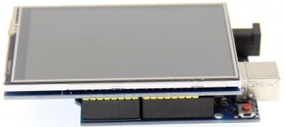
经过一段时间的分析,我在这里继续用另一种方式来表示电位器的模拟值,这次我想体验一个3.5“TFT LCD,我喜欢它的尺寸和可以表示的各种颜色。它是一个组件值得一些项目拥有。当然,这个文档也是关于模拟值的传奇的一部分。
图表
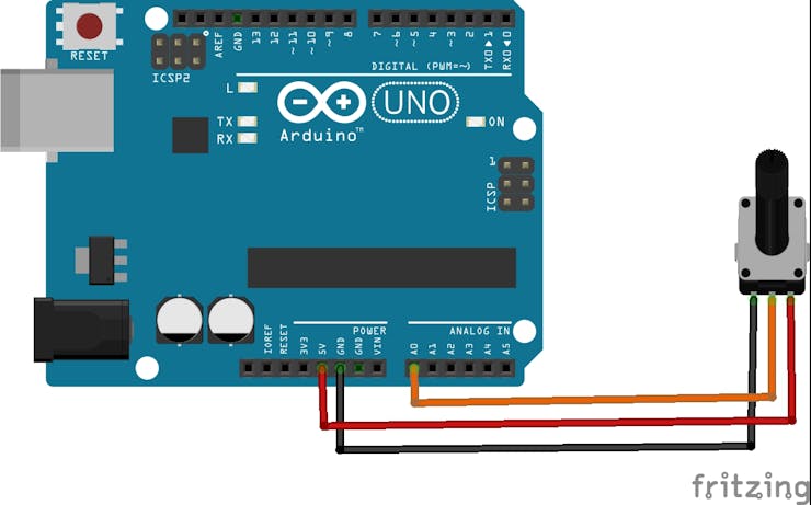
要开发这个项目,不需要复杂的连接或图表,因为电位器必须连接到引脚 A0,然后按照图像参考将屏幕安装在 Arduino UNO 上。
另一个重要的细节:必要的库是LCDWIKI_GUI.h和LCDWIKI_KBV,我喜欢这些库的地方在于易于设计引人注目的元素、文本和背景。
代码的系统
我们包括必要的图形库以使用屏幕并表示必要的形式。
#include  //Core graphics library
#include  //Hardware-specific library
接下来我们为各自的库构建屏幕。
LCDWIKI_KBV my_lcd(ILI9486,A3,A2,A1,A0,A4);
我们定义要使用的颜色。
#define  BLACK   0x0000
#define RED     0xF800
#define GREY 0x2104 // Dark grey 16 bit colour
#define GREEN 0x07E0
#define WHITE 0xFFFF
#define BLUE 0x001F
// Meter colour schemes
#define RED2RED 0
#define GREEN2GREEN 1
#define BLUE2BLUE 2
#define BLUE2RED 3
#define GREEN2RED 4
#define RED2GREEN 5
我们设置变量来控制时间并存储模拟读数的值。
uint32_t runTime = -99999; // time for next update
int reading = 0; // Value to be displayed
现在,在下面几行设置代码中,我们分别初始化屏幕、设置深色背景和设置屏幕旋转方向。
void setup() {
  my_lcd.Init_LCD();
  my_lcd.Fill_Screen(0x0);
  my_lcd.Set_Rotation(1);
}
ringMeter 函数是代码的核心,内部应用数学公式创建各种三角形,两个顶点在内弧上,另一个顶点在外弧上,然后生成一个倒三角形。各种三角形的生成允许构建圆形条并逐渐将颜色应用于它。然后生成居中文本的表示,为此考虑了它所具有的图形数量。
int ringMeter(int value, int vmin, int vmax, int x, int y, int r, byte scheme){
  // Minimum value of r is about 52 before value text intrudes on ring
  // drawing the text first is an option
  x += r; y += r;   // Calculate coords of centre of ring
  int w = r / 4;    // Width of outer ring is 1/4 of radius
  int angle = 150;  // Half the sweep angle of meter (300 degrees)
  int text_colour = 0; // To hold the text colour
  int v = map(value, vmin, vmax, -angle, angle); // Map the value to an angle v
  byte seg = 5; // Segments are 5 degrees wide = 60 segments for 300 degrees
  byte inc = 5; // Draw segments every 5 degrees, increase to 10 for segmented ring
  // Draw colour blocks every inc degrees

  for (int i = -angle; i < angle; i += inc) {
    // Choose colour from scheme
    int colour = 0;
    switch (scheme) {
      case 0: colour = RED; break; // Fixed colour
      case 1: colour = GREEN; break; // Fixed colour
      case 2: colour = BLUE; break; // Fixed colour
      case 3: colour = rainbow(map(i, -angle, angle, 0, 127)); break; // Full spectrum blue to red
      case 4: colour = rainbow(map(i, -angle, angle, 63, 127)); break; // Green to red (high temperature etc)
      case 5: colour = rainbow(map(i, -angle, angle, 127, 63)); break; // Red to green (low battery etc)
      default: colour = BLUE; break; // Fixed colour
    }

    // Calculate pair of coordinates for segment start
    float sx = cos((i - 90) * 0.0174532925);
    float sy = sin((i - 90) * 0.0174532925);
    uint16_t x0 = sx * (r - w) + x;
    uint16_t y0 = sy * (r - w) + y;
    uint16_t x1 = sx * r + x;
    uint16_t y1 = sy * r + y;

    // Calculate pair of coordinates for segment end
    float sx2 = cos((i + seg - 90) * 0.0174532925);
    float sy2 = sin((i + seg - 90) * 0.0174532925);
    int x2 = sx2 * (r - w) + x;
    int y2 = sy2 * (r - w) + y;
    int x3 = sx2 * r + x;
    int y3 = sy2 * r + y;
    if (i < v) { // Fill in coloured segments with 2 triangles
      my_lcd.Set_Draw_color(colour);
      my_lcd.Fill_Triangle(x0, y0, x1, y1, x2, y2);
      my_lcd.Fill_Triangle(x1, y1, x2, y2, x3, y3);
      text_colour = colour; // Save the last colour drawn
    }
    else // Fill in blank segments
    {
      my_lcd.Set_Draw_color(GREY);
      my_lcd.Fill_Triangle(x0, y0, x1, y1, x2, y2);
      my_lcd.Fill_Triangle(x1, y1, x2, y2, x3, y3);
    }
  }

  // Convert value to a string
  char buf[10];
  byte len = 4; if (value > 999) len = 5;
  dtostrf(value, len, 0, buf);
  my_lcd.Set_Draw_color(0, 0,0);
  my_lcd.Fill_Rectangle(x-60, y-15, x+60, y+20);

  // Set the text colour to default
  my_lcd.Set_Text_colour(WHITE);
  my_lcd.Set_Text_Back_colour(BLACK);
  my_lcd.Set_Text_Size(5);
  if (value>999){
    my_lcd.Print_String(String(value), x-60, y-15);
  } else if (value>99 && value<1000){
    my_lcd.Print_String(String(value), x-45, y-15);
  } else if (value>9 && value<100){
    my_lcd.Print_String(String(value), x-30, y-15);
  } else {
    my_lcd.Print_String(String(value), x-15, y-15);
  }
  return x + r;
}
彩虹功能允许您设置用于圆形条的颜色变化。
unsigned int rainbow(byte value){
  // Value is expected to be in range 0-127
  // The value is converted to a spectrum colour from 0 = blue through to 127 = red
  byte red = 0; // Red is the top 5 bits of a 16 bit colour value
  byte green = 0;// Green is the middle 6 bits
  byte blue = 0; // Blue is the bottom 5 bits
  byte quadrant = value / 32;
  if (quadrant == 0) {
    blue = 31;
    green = 2 * (value % 32);
    red = 0;
  }
  if (quadrant == 1) {
    blue = 31 - (value % 32);
    green = 63;
    red = 0;
  }
  if (quadrant == 2) {
    blue = 0;
    green = 63;
    red = value % 32;
  }
  if (quadrant == 3) {
    blue = 0;
    green = 63 - 2 * (value % 32);
    red = 31;
  }
  return (red << 11) + (green << 5) + blue;
}
在循环期间,您需要从电位器读取模拟信号,然后调用 ringmeter 函数进行绘图。
void loop() {
  if (millis() - runTime >= 100L) {
    runTime = millis();
    // Set the position, gap between meters, and inner radius of the meters
    int gap = 4, radius = 120, xpos = my_lcd.Get_Display_Width()/2-radius, ypos = my_lcd.Get_Display_Height()/2-radius;
    int value = analogRead(A5); // read of potentiometer value
    xpos = gap + ringMeter(value, 0, 1020, xpos, ypos, radius, GREEN2RED); // Draw analogue meter
  }
}
结论
所有与用户交互的项目都允许欣赏与代码的各种交互,尤其是这个项目让我探索了 TFT 屏幕的使用、它的颜色甚至基本的图形元素。3.5 英寸的屏幕非常漂亮且易于使用,一旦您从制造商那里获得了技术信息,您仍然可以分享您使用此屏幕的体验。
声明:本文内容及配图由入驻作者撰写或者入驻合作网站授权转载。文章观点仅代表作者本人,不代表电子发烧友网立场。文章及其配图仅供工程师学习之用,如有内容侵权或者其他违规问题,请联系本站处理。 举报投诉
- 相关下载
- 相关文章


