
资料下载


使用MKR IoT Bundle中组件和纸板创建拼图盒
李红
分享资料个
描述
有时让贵重物品远离窥探可能很困难,除非你把它放在一个大保险箱或类似的东西里……但谁有空间呢?
相反,请使用 MKR IoT Bundle 中的组件和一些纸板创建您自己的拼图盒!我们不能保证您财物的安全,但至少对于潜在的小偷来说这将是一种有趣的威慑。
当然,我们建议您将糖果存放在那里……而不是真正的贵重物品。
简而言之
为了打开用伺服电机保持关闭的盒子,您必须转动电位器,直到获得正确的组合。可以通过在线应用程序Blynk设置组合。LED 将帮助您猜测,给您颜色反馈:您越接近颜色越暖。
当猜到正确的组合时,蜂鸣器将开始播放歌曲,而伺服器将打开盒子。
为了创建我们的拼图框,我们需要以下组件:
- 蜂鸣器
- RGB LED
- 3个电位器
- 液晶屏
- 伺服电机
学习目标
- 介绍Blynk互联网平台
- 液晶显示屏的接线和使用
- 用蜂鸣器播放星球大战主题
想知道更多?
本教程是让您熟悉 MKR1000 和 IoT 的一系列实验的一部分。所有实验都可以使用 MKR IoT Bundle 中包含的组件构建。
- 拼图盒
介绍布林克
Blynk是一款流行的物联网移动应用程序,它让我们可以随时随地轻松控制与互联网连接的 Arduino。
它在Kickstarter上成立,并迅速成为该领域最常用的应用程序之一,这要归功于其出色的文档和简单性。
开始使用 Blynk
创建一个新项目真的很容易,只需按照这几个简单的步骤或看一下 Blynk 的官方入门。
成功创建新项目后,您还应该通过邮件收到Auth Token。这是将硬件连接到智能手机所需的唯一标识符。您创建的每个新项目都将拥有自己的 Auth Token。
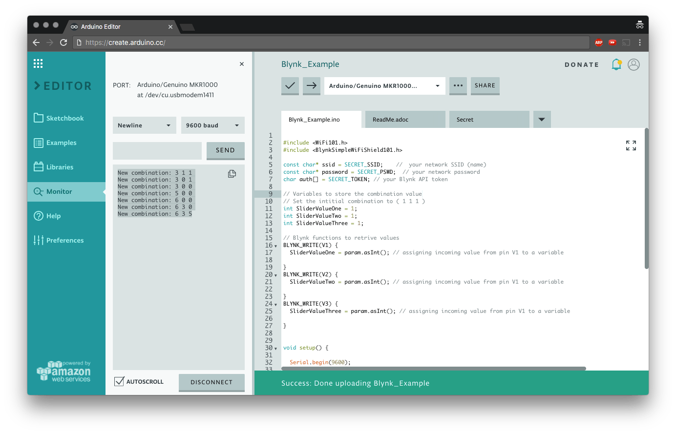
为了将 Arduino 连接到应用程序,我们需要安装Blynk 库。如果您使用的是 Arduino Web 编辑器,则当您将其包含在草图中时,该库将自动下载,否则您可以从库管理器下载该库。
现在我们准备好了。上传此草图并使用滑块查看结果:
#include <WiFi101.h>
#include <BlynkSimpleWiFiShield101.h>
const char* ssid = SECRET_SSID;    //  your network SSID (name)
const char* password = SECRET_PSWD;  // your network password
char auth[] = SECRET_TOKEN; // your Blynk API token
// Variables to store the combination value
// Set the intitial combination to ( 1 1 1 )
int SliderValueOne = 1;
int SliderValueTwo = 1;
int SliderValueThree = 1;
// Blynk functions to retrive values
BLYNK_WRITE(V1) {
 SliderValueOne = param.asInt(); // assigning incoming value from pin V1 to a variable
}
BLYNK_WRITE(V2) {
 SliderValueTwo = param.asInt(); // assigning incoming value from pin V1 to a variable
}
BLYNK_WRITE(V3) {
 SliderValueThree = param.asInt(); // assigning incoming value from pin V1 to a variable
}
void setup() {
 Serial.begin(9600);
 Blynk.begin(auth, ssid, password); // start Blynk functionalities and connect to WiFi
}
void loop() {
 // Variambles to temporarily store the combination
 int Temp_Slider_One_value = SliderValueOne;
 int Temp_Slider_Two_value = SliderValueTwo;
 int Temp_Slider_Three_value = SliderValueThree;
 Blynk.run(); // poll new combination values from the online app
 // check if combination values are changed and print them on the console
 if(Temp_Slider_One_value != SliderValueOne || Temp_Slider_Two_value != SliderValueTwo || Temp_Slider_Three_value != SliderValueThree){
   Serial.print("New combination: ");
   Serial.print(SliderValueOne);
   Serial.print(" ");
   Serial.print(SliderValueTwo);
   Serial.print(" ");
   Serial.println(SliderValueThree);
 }
}
使用液晶屏
是时候连接屏幕了!
LCD 屏幕易于使用,但需要大量电线,因此请准备好证明您的耐心。
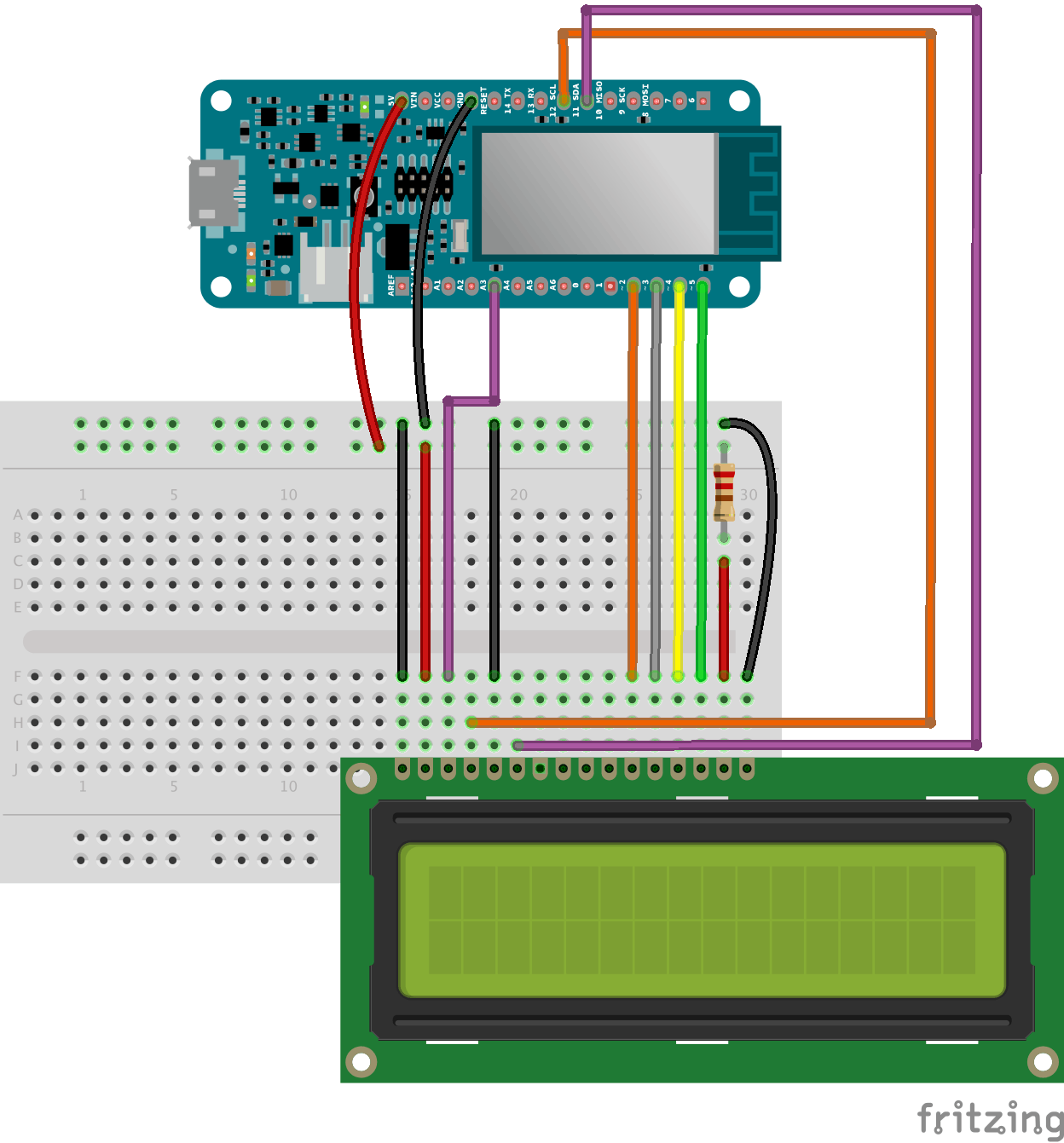
请注意,我们使用的是 5V 电源和 220 欧姆电阻。
可以调节亮度,将模拟引脚 3 的输出值从 0 更改为 255,其中 0 为最大值。
analogWrite(A3, 0);
现在我们可以上传示例草图,看看是否一切正常。
// include the library code:
#include
// initialize the library by associating any needed LCD interface pin
// with the arduino pin number it is connected to
const int rs = 12, en = 11, d4 = 2, d5 = 3, d6 = 4, d7 = 5;
LiquidCrystal lcd(rs, en, d4, d5, d6, d7);
void setup() {
 analogWrite(A3, 0); // Set the brightness to its maximum value
 // set up the LCD's number of columns and rows:
 lcd.begin(16, 2);
 // Print a message to the LCD.
 lcd.print("hello, world!");
}
void loop() {
 // set the cursor to column 0, line 1
 // (note: line 1 is the second row, since counting begins with 0):
 lcd.setCursor(0, 1);
 // print the number of seconds since reset:
 lcd.print(millis() / 1000);
}
添加电位器
要读取电位器的值,我们只需要analogRead() 正确引脚上的一个。我们将它们连接到模拟引脚 0、1、2。
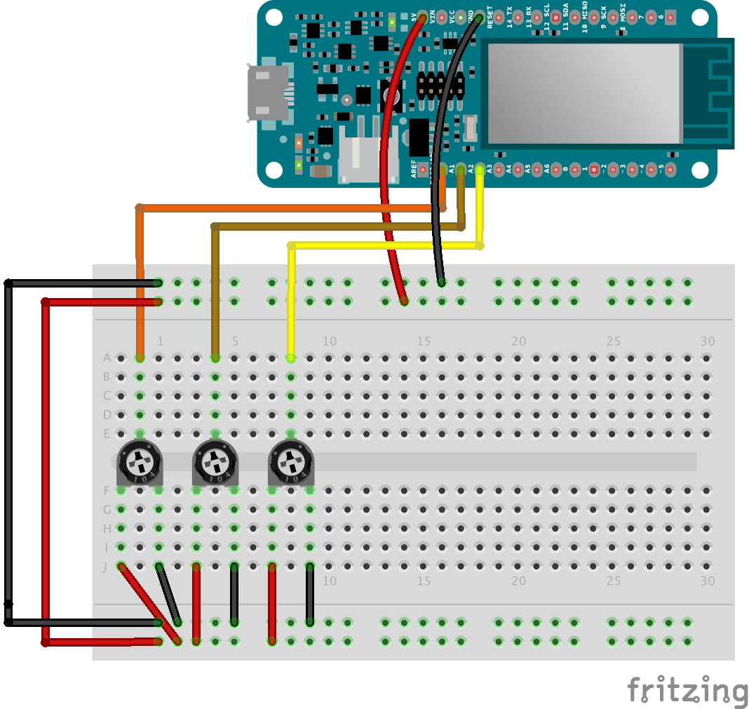
请注意,电位器的值范围从 0 到 1023,因此无法猜测组合。要将这些值从 0 映射到 9,我们将使用该map() 函数,
int PotOne = map(analogRead(A0), 0, 1023, 0, 9);
您可以使用此示例代码在 LCD 屏幕上打印电位器的值。
#include
// LCD screen pins
const int rs = 12,
         en = 11,
         d4 = 2,
         d5 = 3,
         d6 = 4,
         d7 = 5;
LiquidCrystal lcd(rs, en, d4, d5, d6, d7);
void setup() {
 analogWrite(A3, 0); // set the brightness of the LCD screen to the maximum value
 Serial.begin(9600);
 lcd.begin(16, 2); // begin LCD screen with 16 columns and 2 rows
}
void loop() {
 int PotOne = map(analogRead(A0), 0, 1023, 0, 9);
 int PotTwo = map(analogRead(A1), 0, 1023, 0, 9);
 int PotThree = map(analogRead(A2), 0, 1023, 0, 9);
 lcd.setCursor(0, 0);
 lcd.print(PotOne);
 lcd.setCursor(2, 0);
 lcd.print(PotTwo);
 lcd.setCursor(4, 0);
 lcd.print(PotThree);
}
添加 RGB LED
我们将使用 RGB LED 作为反馈来帮助人们猜测组合,他们越接近正确的值,LED 的颜色就越暖和,从蓝色、浅绿色、黄色和红色。
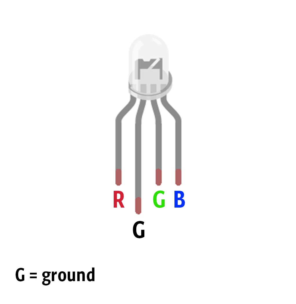
您可以使用此示例草图来查看 RGB 的实际效果!
// RGB LED pins
int redPin = 6;
int greenPin = 8;
int bluePin = 7;
void setup() {
 pinMode(redPin, OUTPUT);
 pinMode(greenPin, OUTPUT);
 pinMode(bluePin, OUTPUT);
 Serial.begin(9600);
}
void loop() {
   setColor(0, 0, 255); // blue
   delay(1000);
   setColor(0, 255, 255); // aqua
   delay(1000);
   setColor(255, 255, 0); // yellow
   delay(1000);
   setColor(255, 0, 0); // Red
   delay(1000);
}
// Send RGB values to the LED pins
void setColor(int red, int green, int blue){
 analogWrite(redPin, red);
 analogWrite(greenPin, green);
 analogWrite(bluePin, blue);
}
将其连接到 Blynk
现在我们准备把东西放在一起:将电路板连接到 Blynk,将电位器连接到 LCD 屏幕,并在组合正确时使 LED 闪烁绿色。
-
请注意,
giveColorFeedback()当每个电位器的绝对值接近某个阈值时,我们将使用该功能设置 LED 的颜色以正确组合。
void giveColorFeedback(int PotOne, int PotTwo, int PotThree){...}
- 我们还将使用这些变量来存储从应用程序发送的值以及组合。
int SliderValueOne = 1;
int SliderValueTwo = 1;
int SliderValueThree = 1;
请注意,初始值设置为 1,只有在您修改应用程序上滑块的值时才会更改。如果您重置板,组合将恢复为默认值。
-
布尔变量
bool start = true;用于检测何时已经猜到组合,以避免在每个循环中重新打开框。
上传此示例草图以查看它的实际效果:
#include
#include
#include
#include
// RGB LED pins
int redPin = 6;
int greenPin = 8;
int bluePin = 7;
const char* ssid = SECRET_SSID;    //  your network SSID (name)
const char* password = SECRET_PSWD;  // your network password
char auth[] = SECRET_TOKEN; // your Blynk API token
// LCD screen pins
const int rs = 12,
         en = 11,
         d4 = 2,
         d5 = 3,
         d6 = 4,
         d7 = 5;
bool start = true;
// Variables to store the combination value
// Set the intitial combination to ( 1 1 1 )
int SliderValueOne = 1;
int SliderValueTwo = 1;
int SliderValueThree = 1;
// Blynk functions to retrive values
BLYNK_WRITE(V1) {
 SliderValueOne = param.asInt(); // assigning incoming value from pin V1 to a variable
}
BLYNK_WRITE(V2) {
 SliderValueTwo = param.asInt(); // assigning incoming value from pin V1 to a variable
}
BLYNK_WRITE(V3) {
 SliderValueThree = param.asInt(); // assigning incoming value from pin V1 to a variable
}
LiquidCrystal lcd(rs, en, d4, d5, d6, d7);
void setup() {
 pinMode(redPin, OUTPUT);
 pinMode(greenPin, OUTPUT);
 pinMode(bluePin, OUTPUT);
 analogWrite(A3, 0); // set the brightness of the LCD screen to the maximum value
 Serial.begin(9600);
 lcd.begin(16, 2); // begin LCD screen with 16 columns and 2 rows
 Blynk.begin(auth, ssid, password); // start Blynk functionalities
}
void loop() {
 // Variambles to temporarily store the combination
 int Temp_Slider_One_value = SliderValueOne;
 int Temp_Slider_Two_value = SliderValueTwo;
 int Temp_Slider_Three_value = SliderValueThree;
 Blynk.run(); // poll new combination values from the online app
 // check if combination values are changed and print them on the console
 if(Temp_Slider_One_value != SliderValueOne || Temp_Slider_Two_value != SliderValueTwo || Temp_Slider_Three_value != SliderValueThree){
   Serial.print("New combination: ");
   Serial.print(SliderValueOne);
   Serial.print(" ");
   Serial.print(SliderValueTwo);
   Serial.print(" ");
   Serial.println(SliderValueThree);
 }
 int PotOne = map(analogRead(A0), 0, 1023, 0, 9);
 int PotTwo = map(analogRead(A1), 0, 1023, 0, 9);
 int PotThree = map(analogRead(A2), 0, 1023, 0, 9);
 lcd.setCursor(0, 0);
 lcd.print(PotOne);
 lcd.setCursor(2, 0);
 lcd.print(PotTwo);
 lcd.setCursor(4, 0);
 lcd.print(PotThree);
 if (start) {
   giveColorFeedback(PotOne, PotTwo, PotThree);
   if (PotOne == SliderValueOne && PotTwo == SliderValueTwo && PotThree == SliderValueThree) {
     blinkGreenLed();
     start = false;
   }
 }
 if(!start) {
   if(PotOne == 0 && PotTwo == 0 && PotThree == 0){
     start = true;
   }
 }
}
// Give feedback based on how close the potentiometer are to the combination value
// The more it's close the warmer is the color of the LED
void giveColorFeedback(int PotOne, int PotTwo, int PotThree) {
 if (abs(PotOne - SliderValueOne) <= 1 && abs(PotTwo - SliderValueTwo) <= 1 && abs(PotThree - SliderValueThree) <= 1 ) {
   // Red
   setColor(255, 0, 0);
 }
 else   if (abs(PotOne - SliderValueOne) <= 3 && abs(PotTwo - SliderValueTwo) <= 3 && abs(PotThree - SliderValueThree) <= 3 ) {
   // yellow
   setColor(255, 255, 0);
 }
   else   if (abs(PotOne - SliderValueOne) <= 4 && abs(PotTwo - SliderValueTwo) <= 4 && abs(PotThree - SliderValueThree) <= 4 ) {
   // aqua
   setColor(0, 255, 255);
 }
 else {
   // blue
   setColor(0, 0, 255);
 }
}
void blinkGreenLed() {
 for (int a = 0; a < 2; a++) {
   for (int b = 0; b <= 255; b += 5) {
     setColor(0, b, 0);
     delay(5);
   }
   for (int b = 255; b >= 0; b -= 5) {
     setColor(0, b, 0);
     delay(5);
   }
 }
 for (int b = 0; b <= 255; b += 5) {
   setColor(0, b, 0);
   delay(5);
 }
}
// Send RGB values to the LED pins
void setColor(int red, int green, int blue){
 analogWrite(redPin, red);
 analogWrite(greenPin, green);
 analogWrite(bluePin, blue);
}
添加蜂鸣器
打开盒子时,我们将使用蜂鸣器播放旋律。更确切地说,我们将播放星球大战主题曲!
连接蜂鸣器很简单:
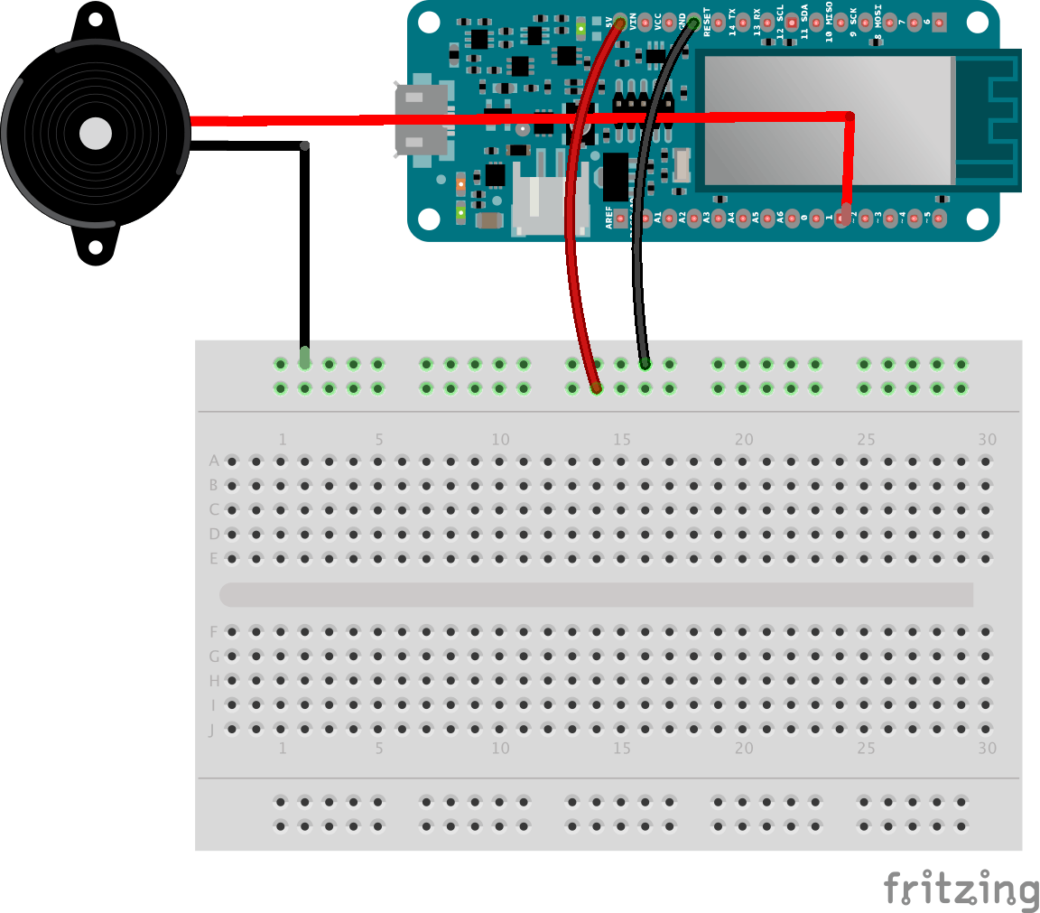
上传此示例代码并收听:
const int c = 261;
const int d = 294;
const int e = 329;
const int f = 349;
const int g = 391;
const int gS = 415;
const int a = 440;
const int aS = 455;
const int b = 466;
const int cH = 523;
const int cSH = 554;
const int dH = 587;
const int dSH = 622;
const int eH = 659;
const int fH = 698;
const int fSH = 740;
const int gH = 784;
const int gSH = 830;
const int aH = 880;
int counter = 0;
#define buzzerPin 1
void setup() {
 pinMode(buzzerPin, OUTPUT);
 Serial.begin(9600);
}
void loop() {
 play_jingle();
 delay(3000);
}
void play_jingle()
{
 beep(a, 500);
 beep(a, 500);
 beep(a, 500);
 beep(f, 350);
 beep(cH, 150);
 beep(a, 500);
 beep(f, 350);
 beep(cH, 150);
 beep(a, 650);
 delay(500);
 beep(eH, 500);
 beep(eH, 500);
 beep(eH, 500);
 beep(fH, 350);
 beep(cH, 150);
 beep(gS, 500);
 beep(f, 350);
 beep(cH, 150);
 beep(a, 650);
 delay(500);
}
void beep(int note, int duration)
{
 //Play tone on buzzerPin
 tone(buzzerPin, note, duration);
 //Stop tone on buzzerPin
 noTone(buzzerPin);
 delay(50);
 //Increment counter
 counter++;
}
添加伺服电机
伺服电机是我们盒子的锁,当密码正确时,我们需要它旋转90度,这样盒子才会打开。
连接伺服只需要三根线。
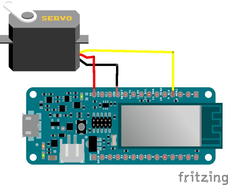
为了将其旋转 90 度,我们将使用以下函数:
#include
int pos = 0;    // variable to store the servo position
Servo myservo;  // create servo object to control a servo
void setup() {
 myservo.attach(9);  // attaches the servo on pin 9 to the servo object
 myservo.write(pos); // set the servo in position 0
}
void loop() {
     open_the_box();
     delay(2000);
     close_the_box();
     delay(2000);
}
void open_the_box(){
     for (pos = 0; pos <= 90; pos += 1) { // goes from 0 degrees to 90 degrees
     myservo.write(pos);              // tell servo to go to position in variable 'pos'
     delay(15);                       // waits 15ms for the servo to reach the position
   }
}
void close_the_box(){
   for (pos = 90; pos >= 0; pos -= 1) { // goes from 90 degrees to 0 degrees
     myservo.write(pos);              // tell servo to go to position in variable 'pos'
     delay(15);                       // waits 15ms for the servo to reach the position
   }
}
请注意,为了将伺服器转回并关闭盒子,您只需将所有电位器转为 0。
建立你的拼图盒
它不会是一个没有盒子的盒子,所以请下载下面的案例文件并将其用作构建您自己的指南。
请注意,我们使用了 2 毫米厚的纸板。
声明:本文内容及配图由入驻作者撰写或者入驻合作网站授权转载。文章观点仅代表作者本人,不代表电子发烧友网立场。文章及其配图仅供工程师学习之用,如有内容侵权或者其他违规问题,请联系本站处理。 举报投诉
- 相关下载
- 相关文章


