
资料下载


用于MiniZed的7段LED显示硬件和VHDL模块
英雄孤寂
分享资料个
描述
介绍
该项目是为 MiniZed 电机控制构建挑战而创建的,最终应用程序是在Adam Taylor的Mini But Mighty项目上构建的。该项目是一个 VHDL 参考设计,用于在可编程逻辑中创建多路复用 7 段显示硬件驱动程序,并展示了如何在没有大量按钮/开关和 LED 的小型电路板(例如 MiniZed)上使用和测试 HDL 硬件模块。该示例介绍了将创建的 VHDL 硬件模块实现到 Mini But Mighty 项目中,以在 7 段显示器上显示实际的 PWM 占空比。
硬件
为了这个项目的需要,我为 5641AS 四位 7 段 LED 显示器创建了一个手工制作的 PCB。段线通过300欧姆电阻连接到表头,每个显示器的共阴极由2N7000 N-MOS晶体管驱动,其栅极通过10k欧姆电阻连接到表头并通过220k欧姆电阻接地。一个 13 针接头(8 段、4 个公共阴极、1 个 GND)通过 Arduino 连接器连接到 MiniZed。
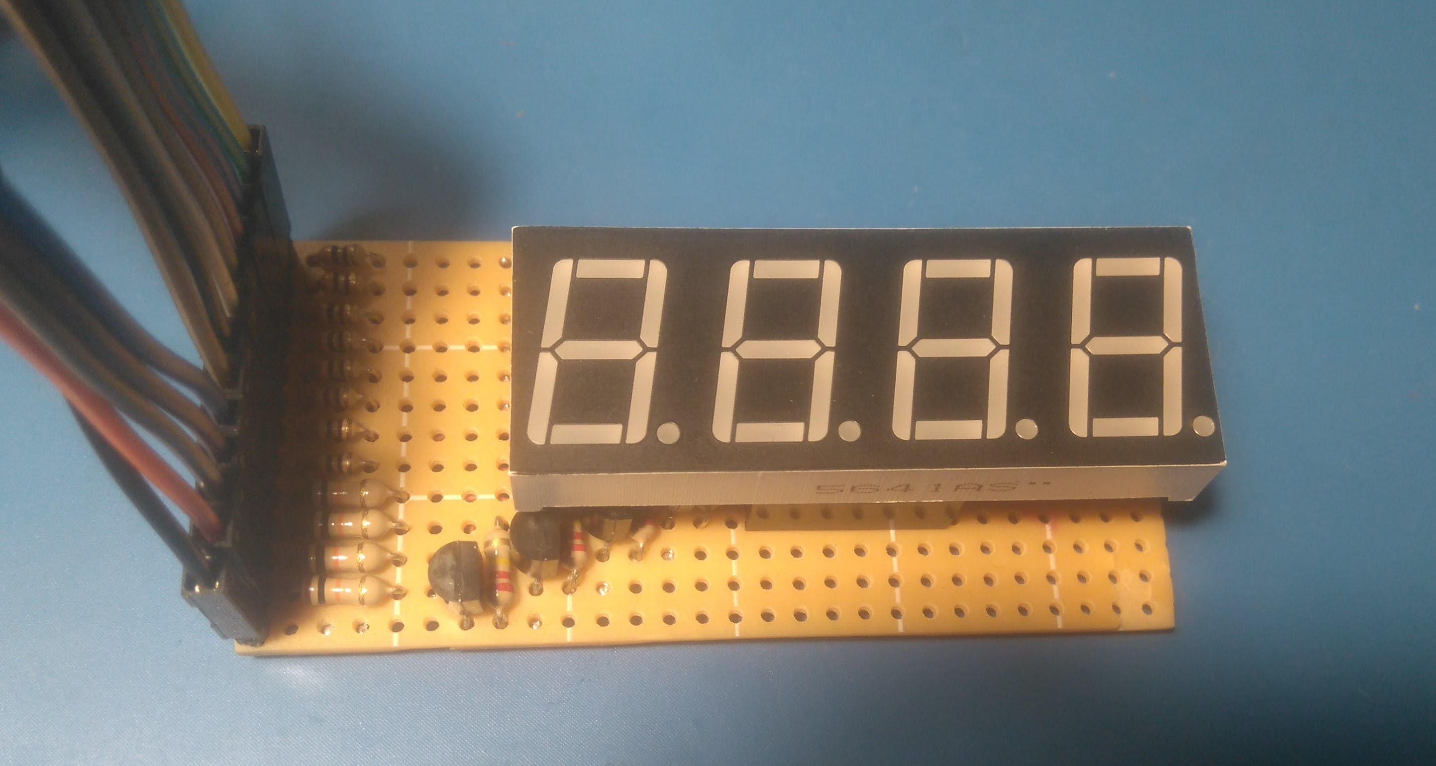
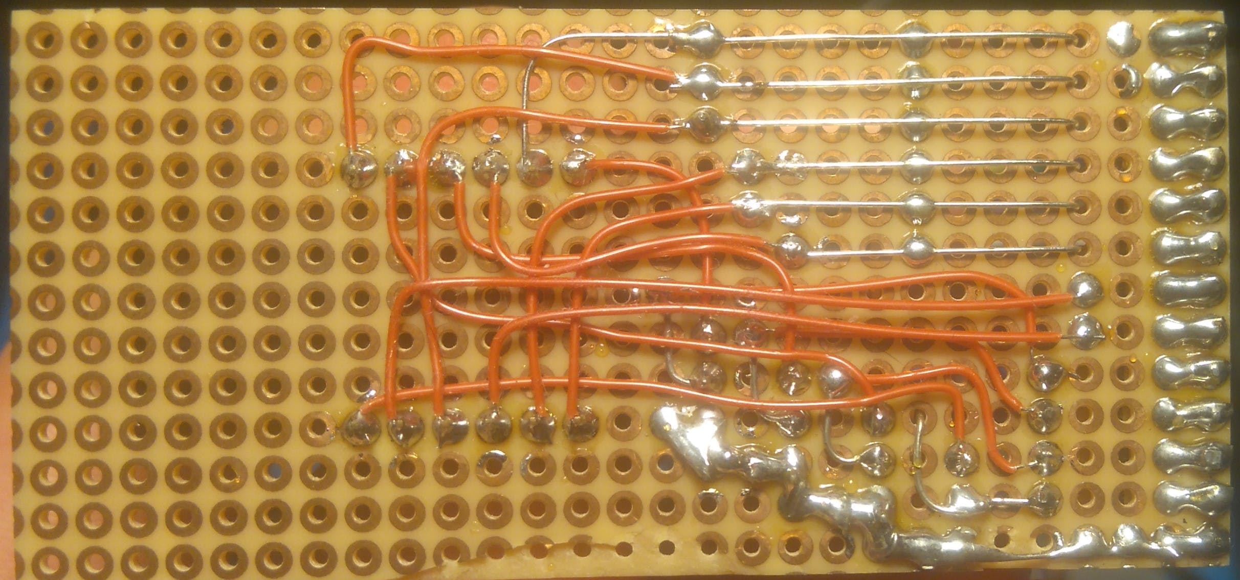
附板子原理图和LED显示屏内部接线图。但是,您可以使用其他具有类似硬件的显示器和电路板。
创建 VHDL 7 段 LCD 显示驱动程序
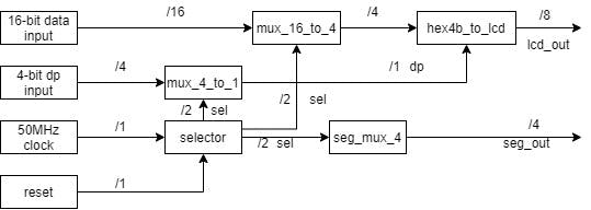
我从框图开始。输入数据是一个 16 位数字,其中每 4 位是一个显示器的编号,因此最低有效 4 位是从右开始第一个显示器的数字,连续的 4 位是下一个显示器,最多 4 个最高有效位是从左数第 4 个显示屏上的数字。因此 16 位二进制数 0b0011001000010000 将显示在显示器 3210 上。第二个 4 位输入用于显示小数精度,其中最低有效位是从左数第一个显示器上的点,最高有效位是从左数第四个显示器。所以 4 位二进制数 0b0001 只会在左起第一个显示器上显示点。其他输入是时钟和复位,该模块设计用于默认 50 MHz 时钟,并提供约 800Hz(每个数字 200 Hz)的显示刷新率的结果。
选择器.vhd
该模块分频并控制多路复用器,2 位输出地址 00 用于第一个显示,11 用于最后一个显示。
library IEEE;
use IEEE.STD_LOGIC_1164.ALL;
-- Uncomment the following library declaration if using
-- arithmetic functions with Signed or Unsigned values
use IEEE.NUMERIC_STD.ALL;
-- Uncomment the following library declaration if instantiating
-- any Xilinx leaf cells in this code.
--library UNISIM;
--use UNISIM.VComponents.all;
entity selector is
Port
(
clk, reset: in std_logic;
sel: out std_logic_vector(1 downto 0)
);
end selector;
architecture Behavioral of selector is
signal state, next_state: unsigned(17 downto 0);
begin
--register
process(clk, reset)
begin
if reset='1' then
state <= (others=>'0');
elsif (clk'event and clk='1') then
state <= next_state;
end if;
end process;
--next state logic
next_state <= state + 1;
--output clk/2^16 for 50MHz around 800 Hz out
sel <= std_logic_vector(state(17 downto 16));
end Behavioral;
mux_4_to_1.vhd
该模块在当前控制的 LED 显示屏上设置点段。
library IEEE;
use IEEE.STD_LOGIC_1164.ALL;
-- Uncomment the following library declaration if using
-- arithmetic functions with Signed or Unsigned values
--use IEEE.NUMERIC_STD.ALL;
-- Uncomment the following library declaration if instantiating
-- any Xilinx leaf cells in this code.
--library UNISIM;
--use UNISIM.VComponents.all;
entity mux_4_to_1 is
Port
(
input  : in std_logic_vector (3 downto 0);
sw     : in std_logic_vector (1 downto 0);
output : out std_logic
);
end mux_4_to_1;
architecture Behavioral of mux_4_to_1 is
begin
with sw select
output <=
input(0)  when "00",
input(1)  when "01",
input(2)  when "10",
input(3)  when "11",
'0' when others;
end Behavioral;
mux_16_to_1.vhd
该模块为当前控制的 LED 显示屏设置 16 位输入的 4 位输出。
library IEEE;
use IEEE.STD_LOGIC_1164.ALL;
-- Uncomment the following library declaration if using
-- arithmetic functions with Signed or Unsigned values
--use IEEE.NUMERIC_STD.ALL;
-- Uncomment the following library declaration if instantiating
-- any Xilinx leaf cells in this code.
--library UNISIM;
--use UNISIM.VComponents.all;
entity mux_16_to_4 is
Port
(
input  : in std_logic_vector (15 downto 0);
sw     : in std_logic_vector (1 downto 0);
output : out std_logic_vector (3 downto 0)
);
end mux_16_to_4;
architecture Behavioral of mux_16_to_4 is
begin
with sw select
output(3 downto 0) <=
input(3 downto 0)   when "00",
input(7 downto 4)   when "01",
input(11 downto 8)  when "10",
input(15 downto 12) when "11",
"0000" when others;
end Behavioral;
hex4b_to_lcd.vhd
将 4 位输入数据转换为当前控制的 LED 显示屏的输出。
library IEEE;
use IEEE.STD_LOGIC_1164.ALL;
-- Uncomment the following library declaration if using
-- arithmetic functions with Signed or Unsigned values
--use IEEE.NUMERIC_STD.ALL;
-- Uncomment the following library declaration if instantiating
-- any Xilinx leaf cells in this code.
--library UNISIM;
--use UNISIM.VComponents.all;
entity hex4b_to_lcd is
Port
(
input:  in  std_logic_vector(3 downto 0);
dot:    in  std_logic;
output: out std_logic_vector(7 downto 0)
);
end hex4b_to_lcd;
architecture Behavioral of hex4b_to_lcd is
begin
with input select
output(6 downto 0) <=
"0111111" when "0000",
"0000110" when "0001",
"1011011" when "0010",
"1001111" when "0011",
"1100110" when "0100",
"1101101" when "0101",
"1111101" when "0110",
"0000111" when "0111",
"1111111" when "1000",
"1101111" when "1001",
"1110111" when "1010", --a
"1111100" when "1011", --b
"0111001" when "1100", --c
"1011110" when "1101", --d
"1111001" when "1110", --e
"1110001" when others; --f
output(7) <= dot;
end Behavioral;
seg_mux_4.vhd
模块切换当前使用的 LED 显示。
library IEEE;
use IEEE.STD_LOGIC_1164.ALL;
-- Uncomment the following library declaration if using
-- arithmetic functions with Signed or Unsigned values
--use IEEE.NUMERIC_STD.ALL;
-- Uncomment the following library declaration if instantiating
-- any Xilinx leaf cells in this code.
--library UNISIM;
--use UNISIM.VComponents.all;
entity seg_mux_4 is
Port
(
input:  in  std_logic_vector (1 downto 0);
enable: in  std_logic;
output: out std_logic_vector (3 downto 0)
);
end seg_mux_4;
architecture Behavioral of seg_mux_4 is
begin
output <= "0000" when (enable = '0') else
"0001" when (input = "00") else
"0010" when (input = "01") else
"0100" when (input = "10") else
"1000" when (input = "11") else
"0000";
end Behavioral;
主.vhd
这是将上述所有模块组合成 7 段显示驱动程序的顶层模块。
library IEEE;
use IEEE.STD_LOGIC_1164.ALL;
-- Uncomment the following library declaration if using
-- arithmetic functions with Signed or Unsigned values
--use IEEE.NUMERIC_STD.ALL;
-- Uncomment the following library declaration if instantiating
-- any Xilinx leaf cells in this code.
--library UNISIM;
--use UNISIM.VComponents.all;
entity main is
Port
(
clk:       in std_logic;
dat_in:    in std_logic_vector(15 downto 0);
dp:        in std_logic_vector(3 downto 0);
reset    : in std_logic;
lcd_out:    out std_logic_vector (7 downto 0);
seg_out:    out std_logic_vector (3 downto 0)
);
end main;
architecture Behavioral of main is
signal num_sel: std_logic_vector (1 downto 0);
signal num_out: std_logic_vector (3 downto 0);
signal dp_out:  std_logic;
begin
u1: entity work.selector
port map(clk=>clk, reset=>reset, sel=>num_sel);
u2: entity work.mux_16_to_4
port map(input=>dat_in, sw=>num_sel, output=>num_out);
u3: entity work.seg_mux_4
port map(input=>num_sel, enable=>'1', output=>seg_out);
u4: entity work.mux_4_to_1
port map(input=>dp, sw=>num_sel, output=>dp_out);
u5: entity work.hex4b_to_lcd
port map(input=>num_out, dot=>dp_out, output=>lcd_out);
end Behavioral;
包含所有模块的 VHDL 代码文件以供使用和分析。
VHDL 模块在 Mini But Mighty 项目中的实现
所以模块是使用 VHDL 创建的,但是如何在 MiniZed 板上测试它呢?较大的 FPGA 板通常有 8 或 16 个输入开关和 LED,用于测试在可编程逻辑中实现的硬件模块的输入和输出。好的,我们在 MiniZed 板上没有足够的 LED 和开关,但我们有更多的东西,Zynq 7000 SoC,它有一个 ARM Cortex - A9 处理器系统 (PS) 和 Xilinx Artix 可编程逻辑 (PL)。我们可以使用和组合这些资源,在芯片内部创建一个灵活的测试环境,并拥有我们需要的尽可能多的输入和输出。这将通过将创建的 VHDL 模块实施到 Mini But Mighty 项目中来呈现。
起点将是Mini But Mighty项目。
Vivado 硬件构建
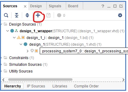
第一步是将我们创建的源添加到项目中。为此,我们使用选项卡源和“加号”按钮。
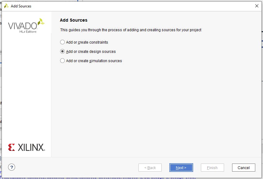
在下一步中,我们选择“添加或创建设计源”。
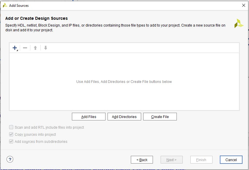
然后单击“添加文件”按钮。
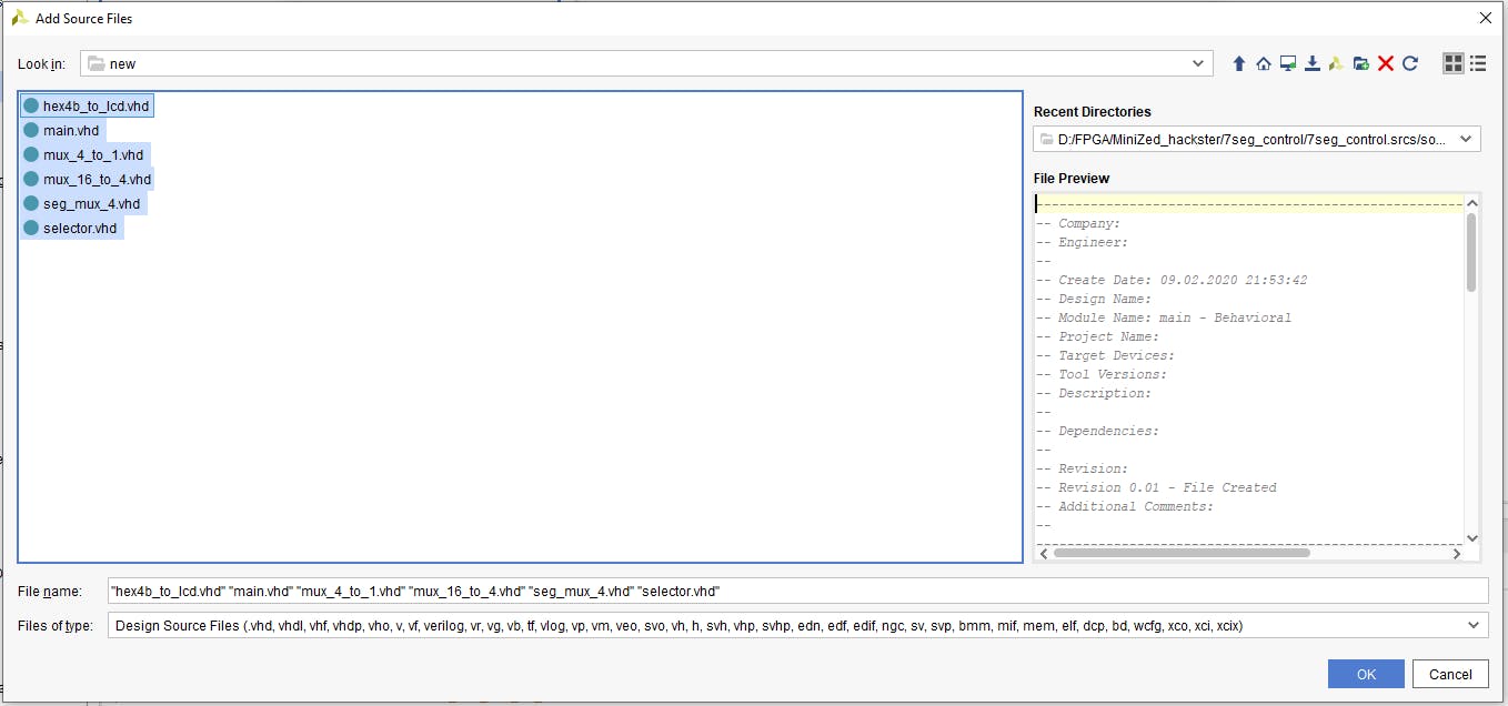
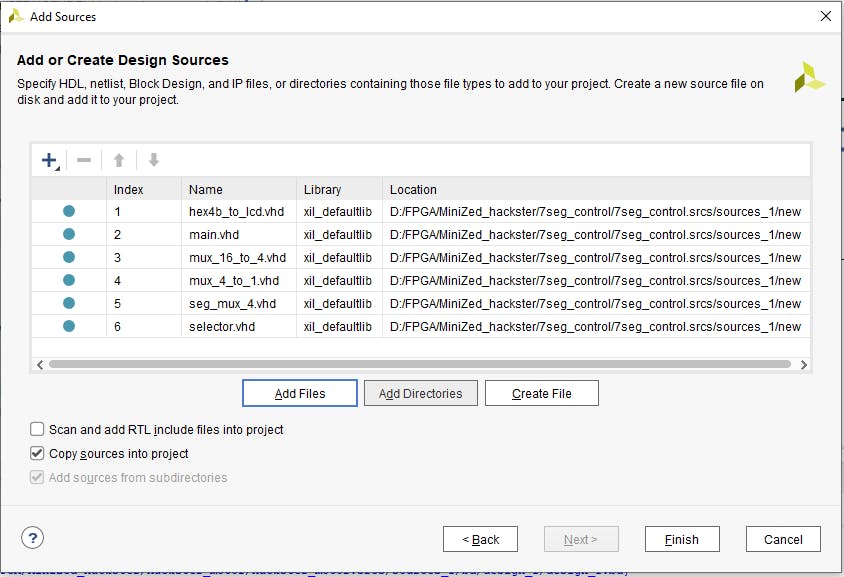
我们选择我们的 VHDL 文件并单击“确定”。
现在在添加源窗口中我们可以看到我们的 VHDL 文件。确保选中“将源代码复制到项目中”,然后接受添加的源代码并转到下一步。
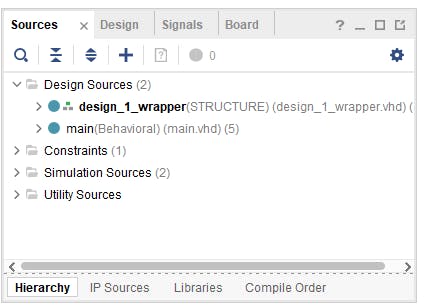
源窗口应该是这样的。
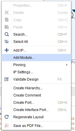
现在在块空间的空白处单击鼠标右键并选择“添加模块”。
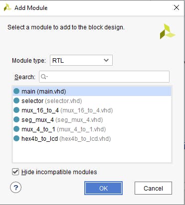
在新窗口中选择“main.vhd”并单击“确定”。
现在在块设计中我们看到创建的 VHDL 模块。
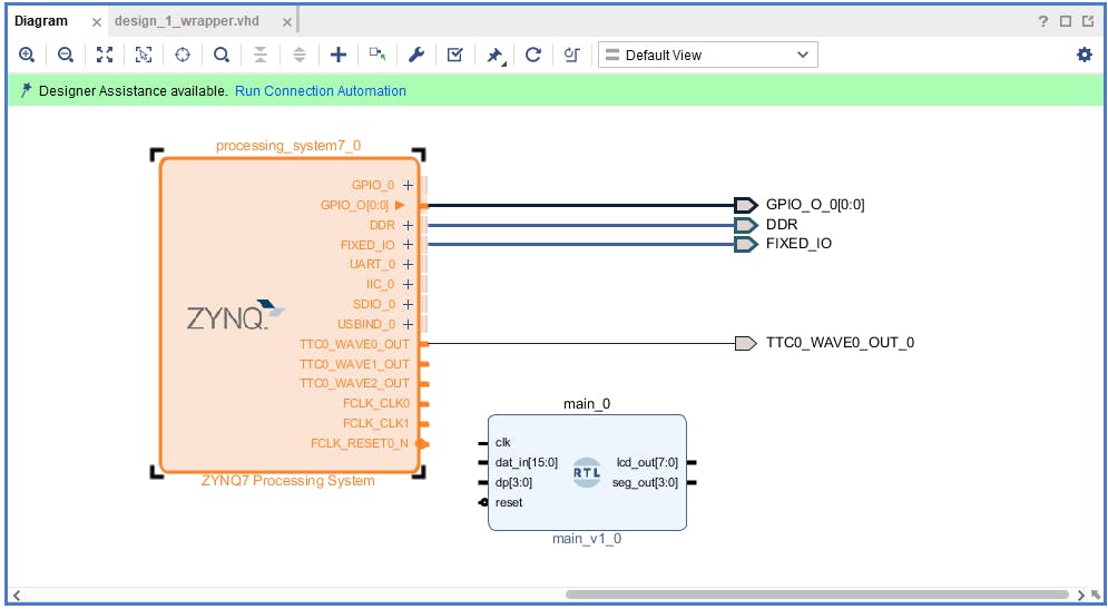
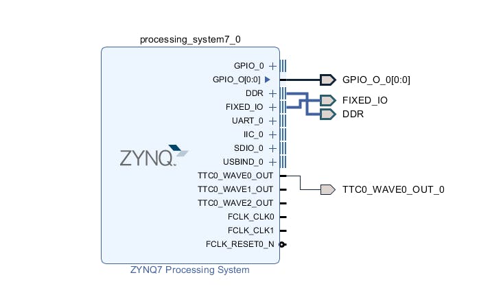
这个模块是简单的 RTL 块,我们需要一些 I/O 来使用它。我们将使用 axi_gpio IP,但首先我们需要配置处理系统。为此,双击 Zynq 块并选择 PS-PL 配置选项卡。
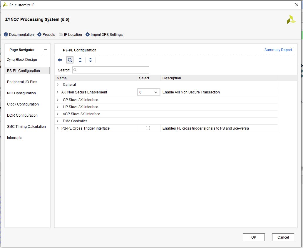
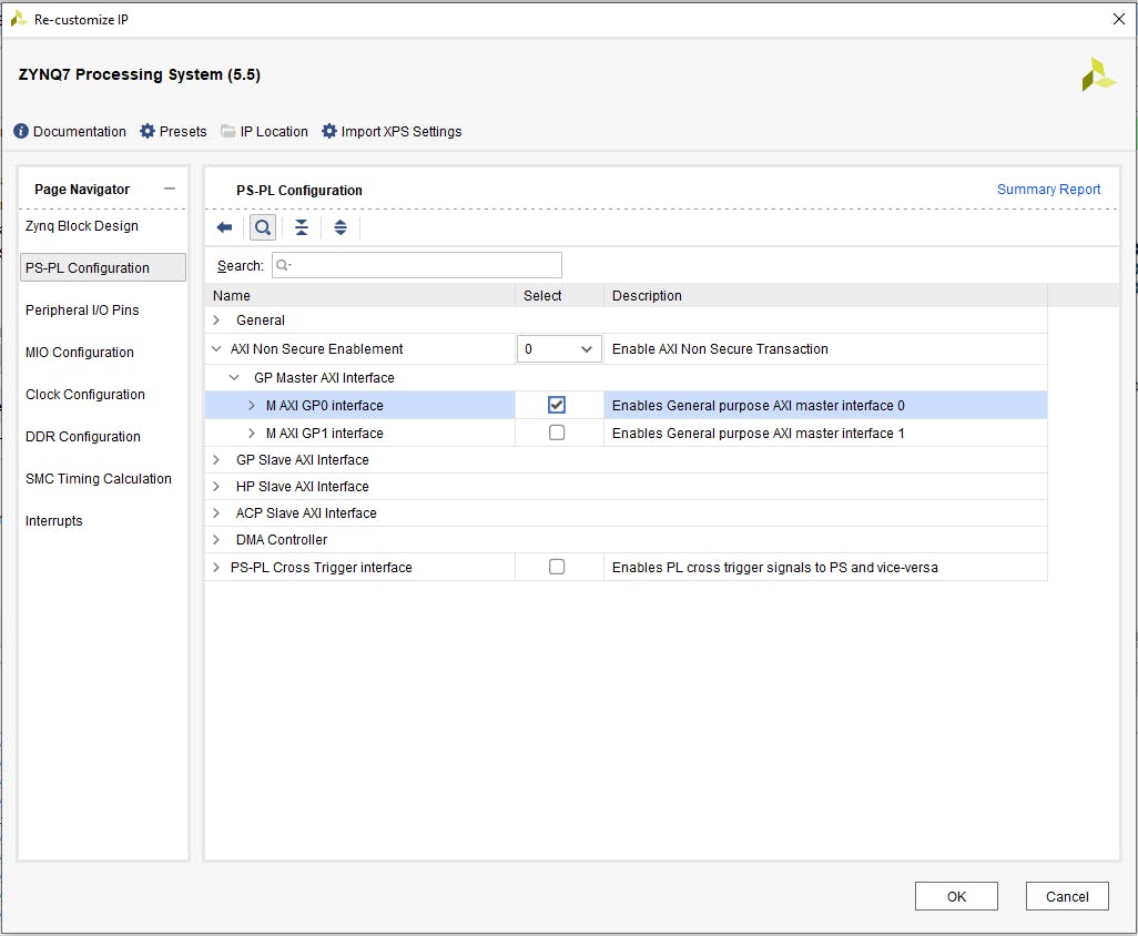
单击“Axi Non Secure Enablement”,然后单击“GP Master AXI Interface”并选择“M AXI GP0 interface”并确认更改。
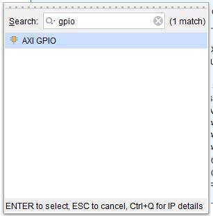
添加 AXI GPIO IP 是通过单击块设计中的“加号”按钮,在搜索窗口中键入“gpio”并选择“AXI GPIO”来完成的。
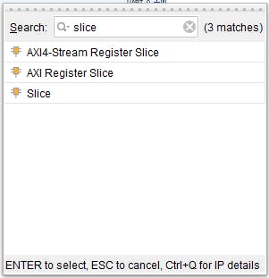
我们还需要两个“切片”块,因此重复最后一步两次,在搜索框中键入“切片”。
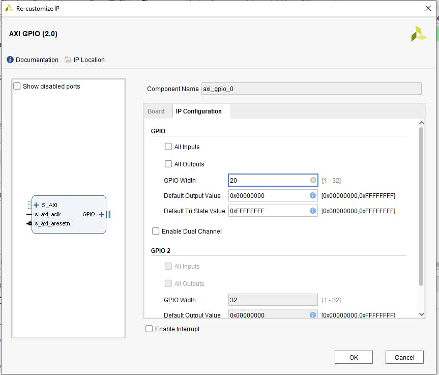
现在我们有了所有的元素,我们需要配置其中的一些。首先是 AXI GPIO,在 IP 设置配置选项卡中手动设置 20 位宽度。
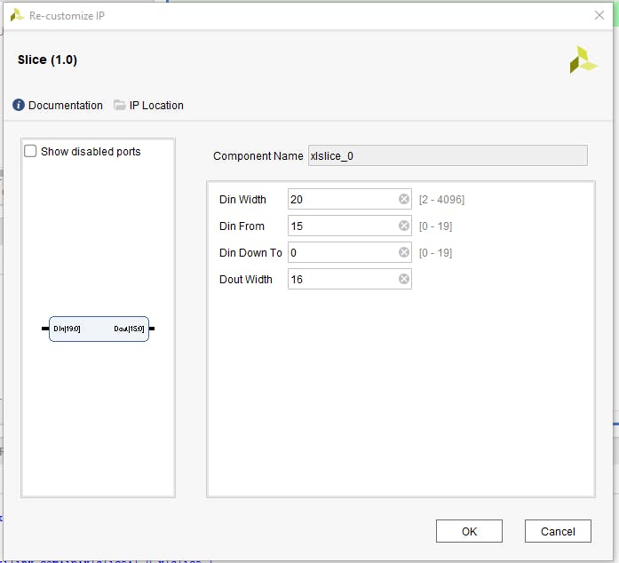
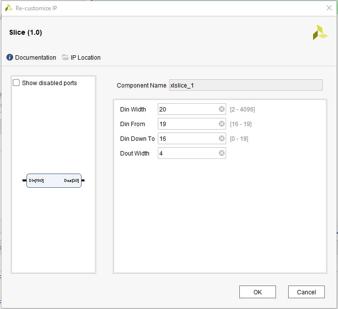
为 20 位输入宽度和 15 到 0 输出配置第一个切片,为 20 位输入宽度和 19 到 16 输出配置第二个切片。
所有块都已配置,因此应建立它们之间的连接。为此,首先单击“运行连接自动化”。

并选择“All automation”(FCLK0 默认配置为 50MHz,它是我们的 RTL 块所需的输入频率)。
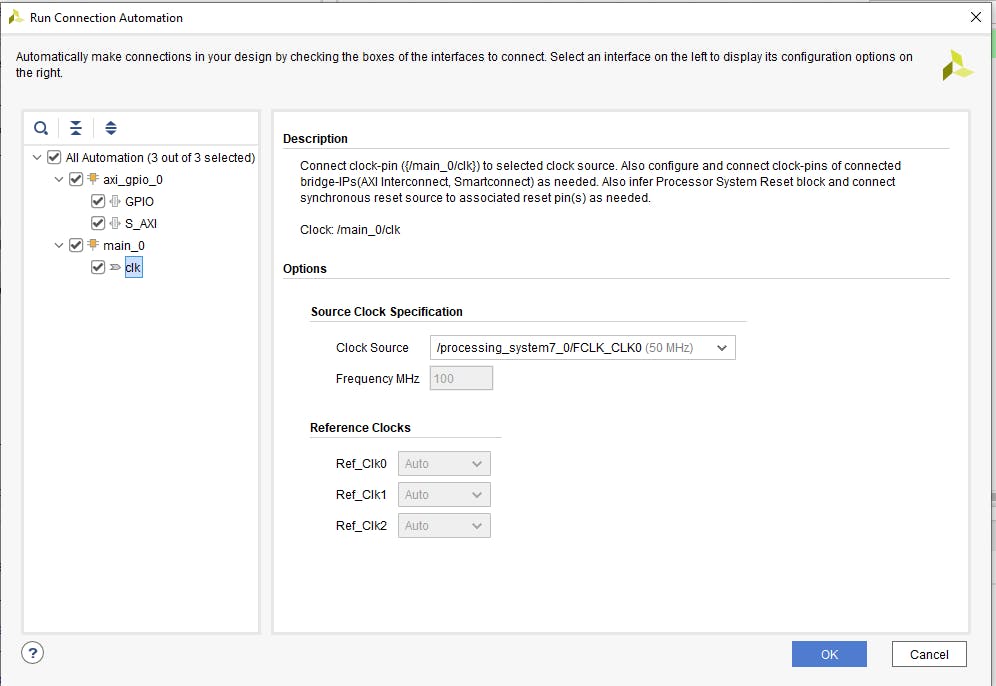
默认情况下,Vivado 会将 VHDL 模块复位连接到 peripheral_aresten,我们需要更正这一点并将复位连接到 peripheral_reset。
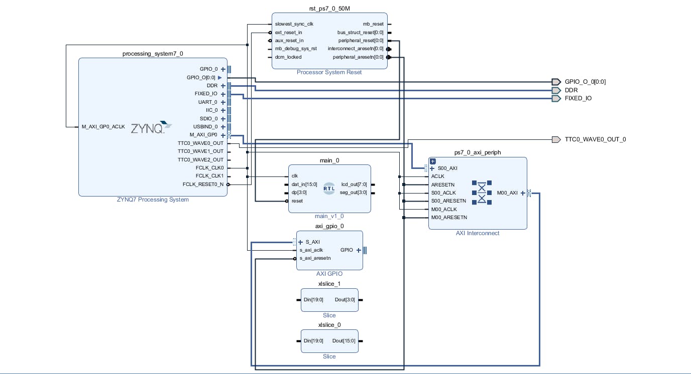
现在我们将切片块连接到 axi_gpio_0 并将切片输出连接到相应的 RTL 模块输入。
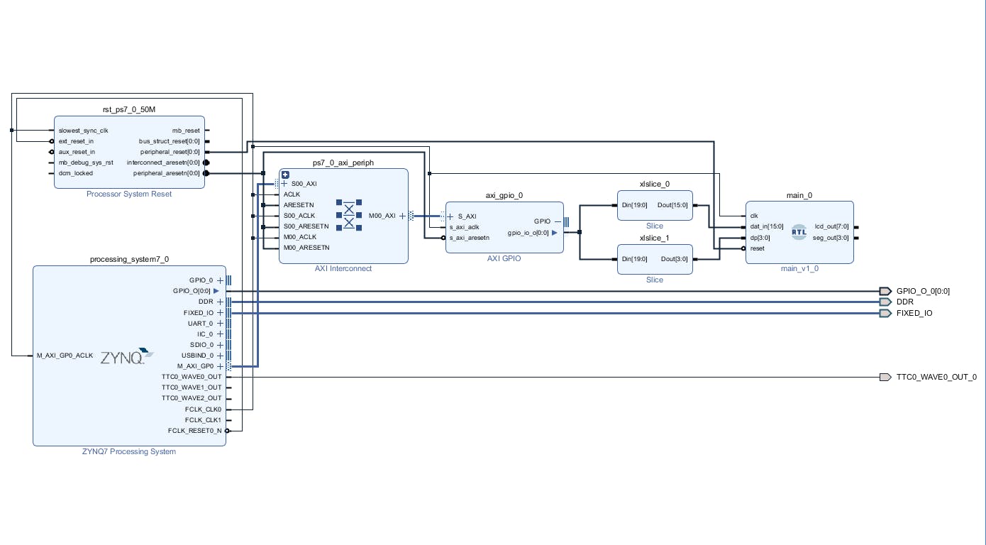
最后一步是使 RTL 模块输出到外部并保存块设计。最终的块设计如下。

在实施、合成和比特流生成之前,必须修改约束条件。显示器的公共部分连接到 Arduino IO0 到 IO7,每个显示器的公共阴极连接到 IO8 到 IO11。因此,我们必须在 io.xdc 文件中添加以下行。
set_property PACKAGE_PIN R8  [get_ports {lcd_out_0[7]}];  # "R8.ARDUINO_IO0"
set_property PACKAGE_PIN P8  [get_ports {lcd_out_0[6]}];  # "P8.ARDUINO_IO1"
set_property PACKAGE_PIN P9  [get_ports {lcd_out_0[5]}];  # "P9.ARDUINO_IO2"
set_property PACKAGE_PIN R7  [get_ports {lcd_out_0[4]}];  # "R7.ARDUINO_IO3"
set_property PACKAGE_PIN N7  [get_ports {lcd_out_0[3]}];  # "N7.ARDUINO_IO4"
set_property PACKAGE_PIN R10 [get_ports {lcd_out_0[2]}];  # "R10.ARDUINO_IO5"
set_property PACKAGE_PIN P10 [get_ports {lcd_out_0[1]}];  # "P10.ARDUINO_IO6"
set_property PACKAGE_PIN N8  [get_ports {lcd_out_0[0]}];  # "N8.ARDUINO_IO7"
set_property PACKAGE_PIN M9  [get_ports {seg_out_0[0]}];  # "M9.ARDUINO_IO8"
set_property PACKAGE_PIN N9  [get_ports {seg_out_0[1]}];  # "N9.ARDUINO_IO9"
set_property PACKAGE_PIN M10 [get_ports {seg_out_0[2]}];  # "M10.ARDUINO_IO10"
set_property PACKAGE_PIN M11 [get_ports {seg_out_0[3]}];  # "M11.ARDUINO_IO11"
set_property IOSTANDARD LVCMOS33 [get_ports -of_objects [get_iobanks 34]];
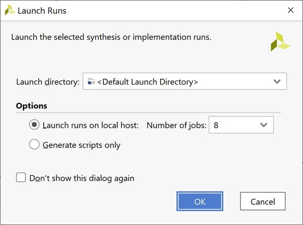
一旦创建了包装器和约束,我们就可以实施设计了。选择 Generate BitStream Option 并在设计编译时等待几分钟。
实施设计
一旦比特流可用,下一步就是导出 XSA 以在 Vitis 中使用。在文件下选择导出-> 导出硬件。
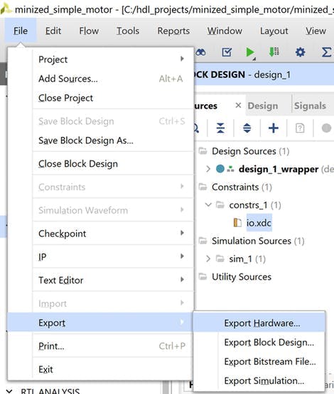
导出硬件
在出现的对话框中选择包含比特流选项
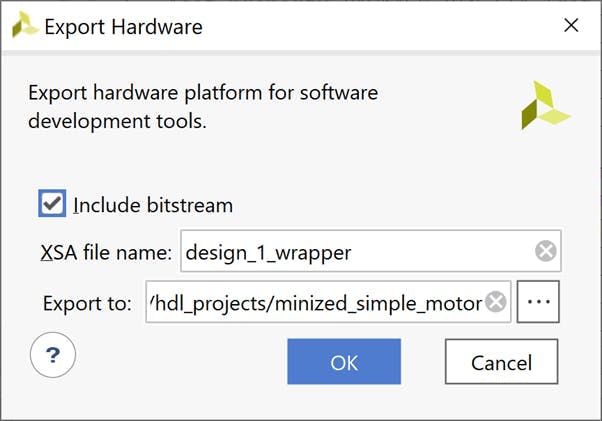
导出 XSA
我们现在准备好打开 Vitis 并更新软件应用程序
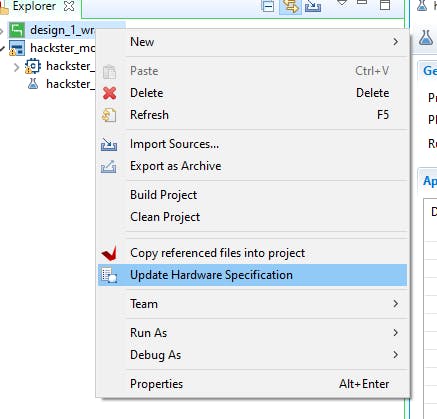
Vitis 软件构建
使用“工具”选项卡启动 Vitis 并选择 Mini But Mighty Workspace。现在我们必须更新硬件平台。在 design_1_wrapper 上单击鼠标右键并选择 Update Hardware Specification。
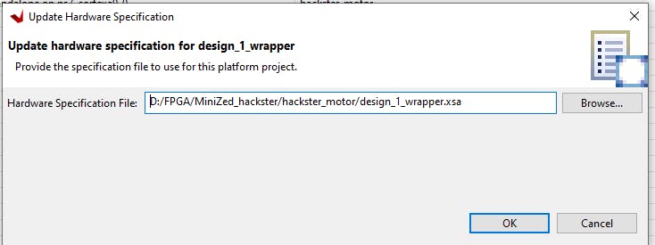
在新打开的窗口中,选择更新的 XSA 文件并确认。
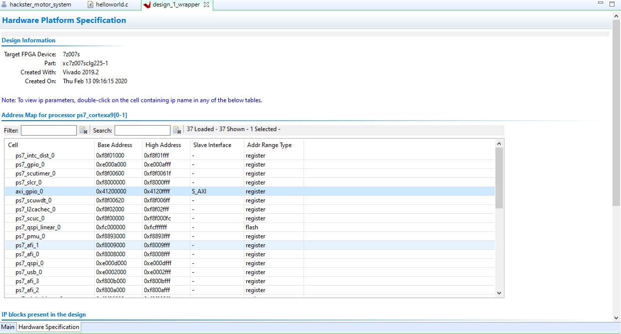
点击build按钮,等待编译结束,然后打开platform.spr文件查看配置,axi_gpio_0应该在Hardware Specification Address Map for processor list中。
现在我们将修改 helloworld.c 应用程序以在我们的显示器上显示实际的 PWM。首先,我们需要为 AXI GPIO 添加额外的库:
#include "xparameters.h"
#include "xgpio.h"
and定义:
#define GPIO_EXAMPLE_DEVICE_ID  XPAR_GPIO_0_DEVICE_ID
#define GPIO_CHANNEL 1
和 GPIO 驱动程序实例:
XGpio GpioPL; /* The Instance of the GPIO Driver */
我们的 7 段 LED 显示和硬件驱动模块默认调整为十六进制数。因此,我们需要创建一个函数,以便在我们的软件应用程序中轻松使用十进制数:
uint8_t set_7seg_dec(uint16_t dec_num, uint8_t dp)
{
uint32_t seg7_out;
seg7_out = 0; // set 0 output
seg7_out = dp<<16; // set decimal point
seg7_out  |= (seg7_out & LED_MASK) | (dec_num % 10)*0x01;
seg7_out  |= (seg7_out & LED_MASK) | (dec_num / 10)%10*0x10;
seg7_out  |= (seg7_out & LED_MASK) | (dec_num / 100)%10*0x100;
seg7_out  |= (seg7_out & LED_MASK) | (dec_num / 1000)%10*0x1000;
XGpio_DiscreteWrite(&GpioPL, GPIO_CHANNEL, seg7_out);
return 0;
}
dec_num - 是 16 位无符号整数,
dp - 是 8 位 usigned int 数字,其中 4 个最低有效位用于小数点,例如 decimal 2 = 0b00000010 将在第二个显示形式右侧显示点。
LED_MASK 是 0x0000FFFF 十六进制数,用于屏蔽 32 位 seg7_out 变量的小数点部分。
最后要做的是修改用于设置输出 PWM 占空比的函数。我们通过将 set_7seg_function 添加到 set_pwm 函数并使用“cycle”变量来实现。变量乘以十是因为我们在第二个显示器上设置了小数点:
void set_pwm(u32 cycle) {
u32 MatchValue;
set_7seg_dec(cycle*10, 2);
MatchValue = (TimerSetup->Interval * cycle) / 100;
XTtcPs_SetMatchValue(&ttcTimer, 0, MatchValue);
}
下面是修改后的 helloworld.c 的完整代码,该文件也可以在 github 存储库中找到。
#include
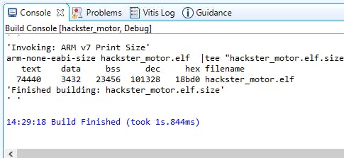
之后我们必须保存文件并构建项目。
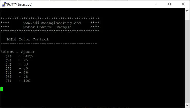
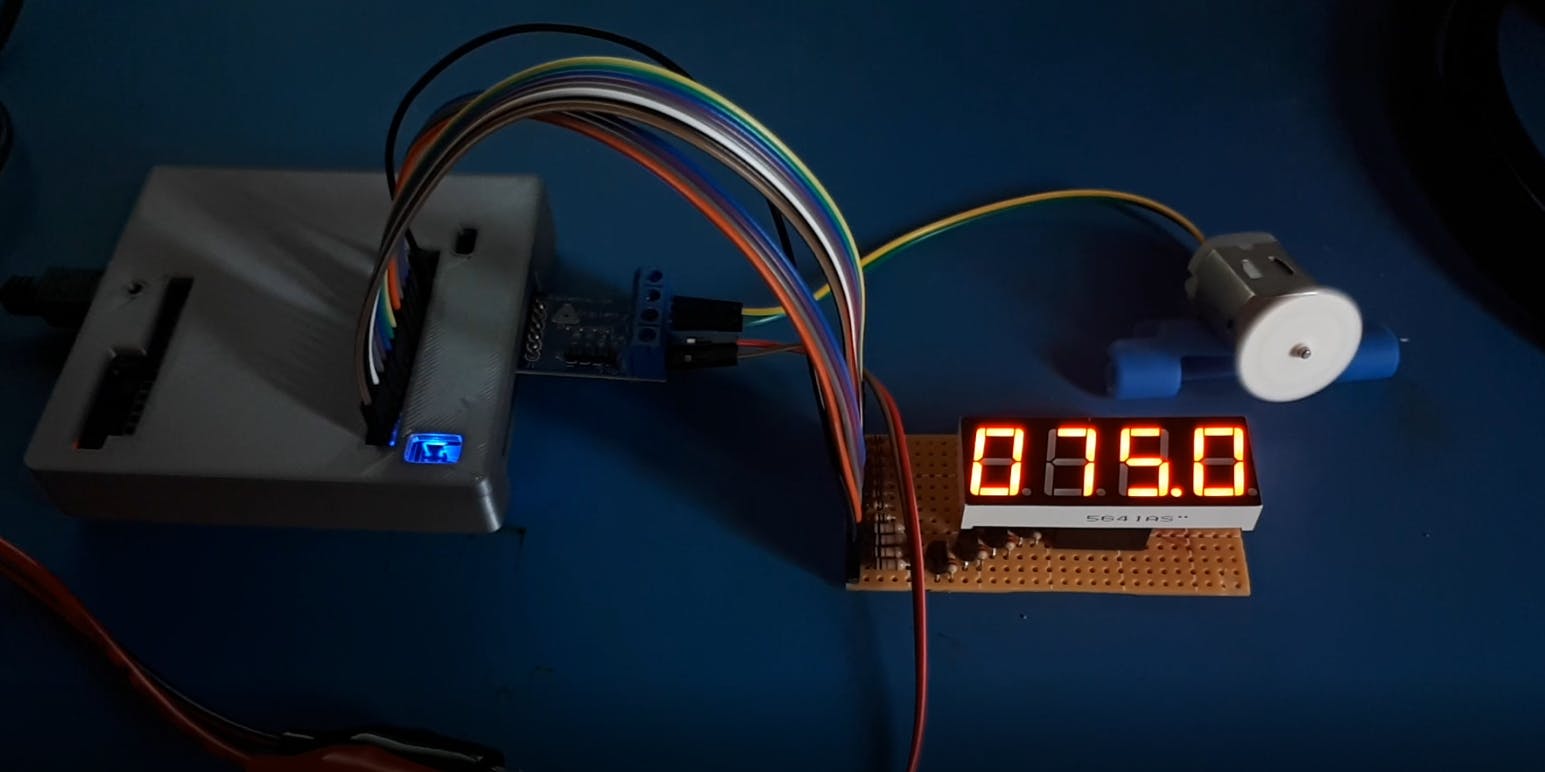
然后,如果没有错误,请单击“运行”按钮并尝试在终端中键入数字以更改 Pmod HB3 输出上的脉冲宽度。实际占空比将显示在 7 段 LED 显示屏上。
包起来
该项目通过四路 7 段 LED 显示示例和 Mini But Mighty 项目的更新展示了我们如何使用 AXI GPIO IP 将我们自己的 VHDL 或其他 HDL 模块用于 Vivado 和 Vitis。可编程逻辑和处理系统的结合是强大的,唯一的限制是想象力。您可以对另一个 HDL 模块使用相同的方法。
声明:本文内容及配图由入驻作者撰写或者入驻合作网站授权转载。文章观点仅代表作者本人,不代表电子发烧友网立场。文章及其配图仅供工程师学习之用,如有内容侵权或者其他违规问题,请联系本站处理。 举报投诉
- 相关下载
- 相关文章


