
资料下载

使用激光雷达和运动捕捉进行自主路径规划
描述
什么是自治如此酷?
在这个项目中,我计划更好地了解如何实现不同的传感器以及获得路径规划的经验。自学期开始以来,我一直在做这方面的大部分工作,我很高兴能有一个工作的结果。
自主机器人技术每年都在增长,我们在任何地方都能看到自主性只是时间问题!特斯拉的汽车是简单自动驾驶的一个很好的例子,因为它们可以轻松规划路径、绘制环境地图并做出决策,但对于处理人类生活和不确定性的完全自动驾驶来说不够可靠或道德。在像自动化仓库这样的受控环境中,这些复杂的决策是不存在的,自主性可以完全冒险。
在这个项目中,我将使用激光雷达作为障碍物检测的主要手段。A* 将用于精确的基于节点的路径规划,Optitrack Motive 软件将用于基于运动捕捉的航位推算。
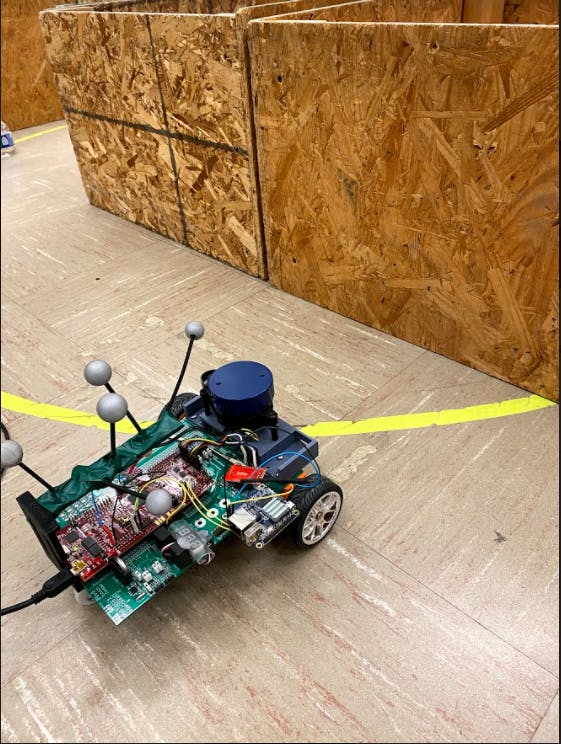
如果您只想查看最终项目,请在底部查看结果。
什么是路径规划?
你如何从一个地方到另一个地方?好吧,你可以随意走,直到你到达目的地,或者你可以计划。规划路径允许布置从一个点开始并在另一个点结束的最佳或功能性路径。想想解决一个迷宫。当然,您可以沿着左墙或右墙一直走到尽头,但这有可能需要很长时间,而且如果没有出口,您肯定有机会永远循环。路径计划可以让您知道是否有通往您想要的位置的方法以及那里更直接的路径。
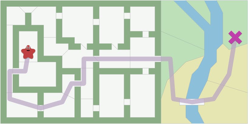
有许多不同类型的路径规划算法,一些示例包括 Dijkstra's、A* 和广度优先搜索。该项目将专注于路径规划的 A* 算法,因为它是上述三个中单个端点最直接的形式。
- 广度优先搜索将同时搜索每个方向的最短路径。这是一个非常有用的算法,但对于路径规划并不理想。
- 使用 Dijkstra 算法而不是广度,因为它有利于成本最低的路径。使您更接近最终目标的节点或路径被优先考虑。
- A* 算法是对一个端点的 Dikstra 的修改和优化版本。

激光雷达有什么作用?
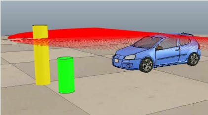
激光雷达只是用于距离测量的传感器。激光从激光雷达中射出,返回所需的时间决定了与传感器的距离。许多 2D 激光雷达,包括我在这个项目中使用的激光雷达,都会在整个传感器周围为您提供许多点和距离,如上图所示。
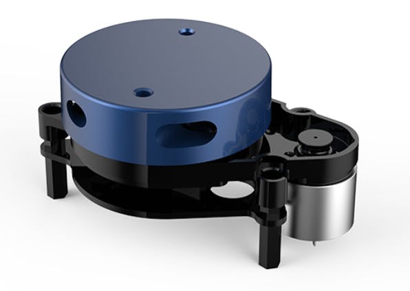
以上是激光雷达可以做什么的一个例子。
动作捕捉?
简单地说,我不需要使用动作捕捉,因为我可以使用电机的测量值来推算机器人汽车;但是,机电一体化室设置了动作捕捉系统。这使得机器人小车的位置非常容易定位;因此,使精确的动作易于执行。我将一个 Orange PI(一种便宜的 Raspberry PI)连接到动作捕捉软件的网络并检索数据。然后,这会将数据发送到微控制器。
机器人汽车电机控制
为了开始这个项目的编码部分,我将回顾控制直流电机的代码
// Read the motor rotation
    RightWheel = readEncRight();
    LeftWheel = -readEncLeft();

    // distance ft
    XLeftK = 1/(radftL/LeftWheel);
    XRightK = 1/(radftR/RightWheel);
    // vel ft/s
    VLeftK = (XLeftK - XLeftK1)/0.004;
    VRightK = (XRightK - XRightK1)/0.004;
下面的代码读取相应电机的旋转角度,并使用已知的车轮半径,我可以计算出车轮的行驶距离和速度。
float readEncLeft(void) {
    int32_t raw = 0;
    uint32_t QEP_maxvalue = 0xFFFFFFFFU; //4294967295U
    raw = EQep1Regs.QPOSCNT;
    if (raw >= QEP_maxvalue/2) raw -= QEP_maxvalue; // I don't think this is needed an           d never true
    // 5 North South magnet poles in the encoder disk so 5 square waves per one revolution of the
    // DC motor's back shaft. Then Quadrature Decoder mode multiplies this by 4 so 20 counts per one rev
    // of the DC motor's back shaft. Then the gear motor's gear ratio is 30:1.
    return (raw*(1/(20*30/(2*PI))));
}
一旦每 1ms 计算一次速度和距离,我就实现了一个 PI 控制器,以通过确定的 Vref 和 Turn 平滑地控制电机。
// PI

    eturn = turn + (VLeftK - VRightK);

    ekLeft = Vref - VLeftK - (Kturn*eturn);
    IkLeft = IkLeft1 + 0.004*((ekLeft + ekLeft1)/2);
    uLeft = (Kp*ekLeft) + (Ki*IkLeft);

    ekRight = Vref - VRightK + (Kturn*eturn);
    IkRight = IkRight1 + 0.004*((ekRight + ekRight1)/2);
    uRight = (Kp+ekRight) + (Ki*IkRight);
在 PI 控制器计算之后,我只需将电机设置为确定的 uLeft 和 uRight 值。我还必须使 uLeft 和 uRight 饱和,以防积分结束是 PID 控制的常见问题。我确保将当前状态与过去状态相同。
//integral wind up
    if(fabs(uLeft) >= 10) {
        IkLeft = IkLeft1;
    }
    if(fabs(uRight) >= 10){
        IkRight = IkRight1;
    }


    setEPWM2A(uRight);
    setEPWM2B(-uLeft);

    //states
    XLeftK1 = XLeftK;
    XRightK1 = XRightK;
    IkLeft1 = IkLeft;
    IkRight1 = IkRight;
    ekLeft1 = ekLeft;
    ekRight1 = ekRight;
激光雷达数据设置
要使用激光雷达,我们必须找出我们从传感器获得的数据以及如何组织它。数据通过 SPIRXD 从激光雷达发送到微控制器。为与激光雷达通信而编写的代码使用状态来检查和读取传感器的初始化和数据。
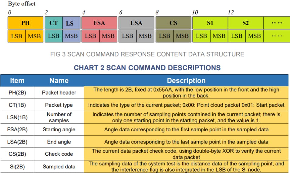
来自 LIDAR 的数据以数据包的形式发送,所有数据包都以数据包头 0xAA 开头。这是我们首先检查的内容,如果找到 0x55AA,我们可以进入状态 2,否则我们继续寻找。
if(state == 0) { //check 0xaa
        if(data == 0xAA) {
            state = 1;
        } else {
            state = 0;
        }
} else if (state == 1) {//check 0x55
        if(data == 0x55) {
            state = 2;
        } else {
            state = 0;
        }
接下来,我们查看发送的数据包是起始数据包还是点云数据包,0x00。如果是我们推进的点云包。
} else if (state == 2) {//check 0x0
        if (data == 0x0) {
            state = 3;
//            packetcount+=1;
        } else {
            state = 0;
        }
然后我们读取数据包中的样本数量并记录下来。
} else if (state == 3){ //read sample size
        sampleSize = data;
        state = 4;
}
接下来,是读取并记录开始和结束角度。
} else if (state == 4) {//read starting angle lsb
        startangleLSB = data;
        state = 5;
    } else if (state == 5) {//record starting angle
            start_angle = ((((data<<8)| startangleLSB)>>1)&0x7FFF)/64.0;
        state = 6;
    } else if (state == 6) { //read end angle
            endLSB = data;
        state = 7;
    } else if (state == 7) {//record end angle
        end_angle = ((((data<<8)| endLSB)>>1)&0x7FFF)/64.0;

        if (end_angle < start_angle) {
            cor_end = end_angle + 360;
        } else {
            cor_end = end_angle;
        }
        delta_angle = cor_end-start_angle;
        state = 8;
}
最后,我们可以记录 LIDAR 数据点并告诉微控制器忽略检查,因为我们假设只要 LIDAR 运行它就会保持不变。我们确保使用乒乓缓冲区来确保我们有足够的时间来记录数据并且不会遗漏任何数据。
} else if (state == 8) {//record samples and ignore the check code
        if(position > 1) {
            if (dis_state == 0){
                dLSB = data;
                dis_state = 1;
            } else if (dis_state == 1){

                    float raw_angle = (delta_angle)/(sampleSize - 1) * (sampleindex) +start_angle;
                    sampleindex = sampleindex+1;
                    if(sampleindex == sampleSize) {
                        sampleindex = 0;
                    }
                    pts[arrayIndex].rawAngle = raw_angle;
                    if(dist == 0){
                        cal_angle = raw_angle;
                    } else {
                        cal_angle = raw_angle + atan(21.8*(155.3-dist)/(155.3*dist))*57.296;
                    }
                    pts[arrayIndex].cor_angle = cal_angle;

                    if (pingpongflag == 1) {
                        pingpts[((int16_t)(cal_angle + 0.5))%360].distance = dist;
                        pingpts[((int16_t)(cal_angle + 0.5))%360].timestamp = numTimer0calls;
                    } else {
                        pongpts[((int16_t)(cal_angle + 0.5))%360].distance = dist;
                        pongpts[((int16_t)(cal_angle + 0.5))%360].timestamp = numTimer0calls;
                    }
                    dis_count += 1;
                    dis_state = 0;
                    if (arrayIndex < 599) {
                        arrayIndex += 1;
                    }
            }
        }
现在我们有数据了!我们还确保获取数据并将其组织成一个很好的结构,说明角度、距离和时间戳。我还包括了为我的机器人创建的自定义 3D 零件。
A* 算法
由于我们有激光雷达工作,是时候让 A* 算法为机器人的路径规划工作了。如前所述,A* 是 Dijkstra 算法的修改版本。
A* 和 Dijkstra 算法都使用优先级队列来优先考虑成本较低或较高的路径。优先级队列与普通队列不同,它基于先进先出,而优先级队列按“最高优先级”、最低成本组织其队列。有关优先级队列背后的代码的更多信息,请访问下面的链接。
http://pages.cs.wisc.edu/~vernon/cs367/notes/11.PRIORITY-Q.html
解释 A* 算法的最简单方法是,它既需要从起点的实际距离,又需要估计到目标的距离。
f=g+h
上面的等式是 A* 的基础,因为 F 是节点的总成本,G 是当前节点和起始节点之间的距离,H 是启发式距离,即从当前节点到结束节点的估计距离。完整的 A* 算法函数可以在下面的源代码中找到。我将分享帮助我为我的地图创建算法的伪代码。
// A*
Function A*(start,goal)

// Initialize the closed list, the set of nodes already evaluated Closedset = the empty set
//Initialize the open list, the set of tentative nodes to be evaluated //initially containing the start node
Start g score = 0 Start
f score = g score plus h “Manhattan distance from start to goal”
Openset = {start} came_from = empty
// The map of the navigated nodes
while the open list is not empty
    Find the node with the least f on the open list, call it "q"
    Pop q off the open list
    Generate q's 4 neighbors
    For each neighbor  If neighbor is the goal, stop the search
        neighbor.g = q.g + distance between neighbor and q
        // h distance is the “Manhattan” distance on a square grid
        neighbor.h = distance from goal to neighbor
        neighbor.f = neighbor.g + neighbor.h

        If a node with the same position as neighbor is in the OPEN list \  which has a lower f than neighbor, skip adding this neighbor

        if a node with the same position as neighbor is in the CLOSED list \  which has a lower f than neighbor, skip adding this neighbor

        otherwise, add the node to the open list and came_from[neighbor] = q //set neighbor’s parent equal to q
    end
    push q on the closed list
end
运行 A* 算法
完成我的 A* 代码后,我现在可以将地图设置为我想要的任何大小,我选择了 16X11,因为这是我将要驾驶的网格的大小。
int startRow = 4;
int startCol = 5;
int endRow = 15;
int endCol = 1;
char mapCourseStart[176] =      //16x11
{   '0', '0', '0', '0', '0', '0', '0', '0', '0', '0', '0',
    '0', '0', '0', '0', '0', '0', '0', '0', '0', '0', '0',
    '0', '0', '0', '0', '0', '0', '0', '0', '0', '0', '0',
    '0', '0', '0', '0', '0', '0', '0', '0', '0', '0', '0',
    'x', 'x', 'x', 'x', '0', '0', '0', 'x', 'x', 'x', 'x',    //start row
    '0', '0', '0', '0', '0', '0', '0', '0', '0', '0', '0',
    '0', '0', '0', '0', '0', '0', '0', '0', '0', '0', '0',
    '0', '0', '0', '0', '0', '0', '0', '0', '0', '0', '0',
    '0', '0', '0', '0', '0', '0', '0', '0', '0', '0', '0',
    '0', '0', '0', '0', '0', '0', '0', '0', '0', '0', '0',
    '0', '0', '0', '0', '0', '0', '0', '0', '0', '0', '0',
    '0', '0', '0', '0', '0', '0', '0', '0', '0', '0', '0',
    '0', '0', '0', '0', '0', '0', '0', '0', '0', '0', '0',
    '0', '0', '0', '0', '0', '0', '0', '0', '0', '0', '0',
    '0', '0', '0', '0', '0', '0', '0', '0', '0', '0', '0',
    '0', '0', '0', '0', '0', '0', '0', '0', '0', '0', '0'   };

if (PathFunction == 1){ // 1 for A* path
            // create the map
            mapRowSize = 16;
            mapColSize = 11;
            //reset Search flag
            obsSearch = 0;
            if(astarC == 0){   //Starting position
                startRow = 4;
                startCol = 5;
            }else{
                //floor the astar start point
                startRow = floorf(ROBOTps.y);
                startCol = floorf(ROBOTps.x);
            }
            astarC++;
            int i = 0;
            for(i = 0; i//*mapcolsize;>copy m1 into map for solving
                map[i] = mapCourseStart[i];
            }
上面的代码创建了一个 16X11 的地图,并设置了一个起始行和起始列,并复制了一个没有障碍物的预定地图,这些地图将在添加时更新。
astar(startRow,startCol,endRow,endCol); // solve path
然后,我们使用指定的端点运行 A* 函数。这应该导致路径。经过几次检查以确保起点和终点在界限内并且它们不在障碍物上。A* 函数可以返回 3 个值 1、2 或 3 中的 1 个。
retvalue = astar(startRow,startCol,endRow,endCol);
                    if (retvalue == 1) {
                        serial_printf(&SerialA,"   pathLength %d\r\n", pathLen);
                        int i = 0;
                        for(i = 0; i< pathLen; i++)     //put solution on map
                        {
                            int mapIdx = pathRow[i]*mapColSize + pathCol[i];
                            map[mapIdx] = '-';
                        }
                        //put path nodes into structure node_path
                        int p = 0;
                        for(p = 0; p < pathLen; p++)
                        {
                            path[p].row = pathRow[(pathLen-1)-p];
                            path[p].col = pathCol[(pathLen-1)-p];
                        }

                        //print map with solution
                        i = 0;
                        int j = 0;
                        for(i=0; i                        {
                            for(j = 0; j                            serial_printf(&SerialA,"   %c  ", map[i*mapColSize+j]);
                            serial_printf(&SerialA,"\r\n");
                        };>;>
如果它返回 1,我们有一个路径!然后我们采用这条路径并将其添加到解决方案地图并打印解决方案。这条路径从结尾开始,一直到开头,所以我确保创建一个路径数组,以便将来更容易使用。
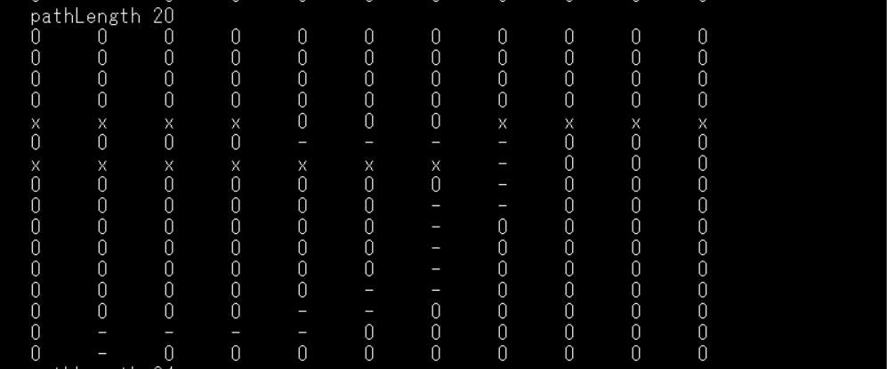
如果函数返回 2,那么它已经在这一点上,我们打印一个 ERROR。
} else if (retvalue == 2) {
                        serial_printf(&SerialA,"\r\n");
                        serial_printf(&SerialA,"\r\n");
                        serial_printf(&SerialA,"\r\n");
                        serial_printf(&SerialA,"\r\n");
                        serial_printf(&SerialA,"!!!!!!!!!!!!!!!!Error!!!!!!!!!!!!!!!\r\n");
                        serial_printf(&SerialA,"Already at this point.  No Astar needed.\r\n");
                        serial_printf(&SerialA,"!!!!!!!!!!!!!!!!Error!!!!!!!!!!!!!!!\r\n");
                        serial_printf(&SerialA,"\r\n");
                        serial_printf(&SerialA,"\r\n");
                        serial_printf(&SerialA,"\r\n");
                        serial_printf(&SerialA,"\r\n");
如果未找到机器人的有效路径,该函数将返回 3。
} else {
                        serial_printf(&SerialA,"\r\n");
                        serial_printf(&SerialA,"\r\n");
                        serial_printf(&SerialA,"\r\n");
                        serial_printf(&SerialA,"\r\n");
                        serial_printf(&SerialA,"!!!!!!!!!!!!!!!!Error!!!!!!!!!!!!!!!\r\n");
                        serial_printf(&SerialA,"No Path Found Obstacle in the path.\r\n");
                        serial_printf(&SerialA,"!!!!!!!!!!!!!!!!Error!!!!!!!!!!!!!!!\r\n");
                        serial_printf(&SerialA,"\r\n");
                        serial_printf(&SerialA,"\r\n");
                        serial_printf(&SerialA,"\r\n");
                        serial_printf(&SerialA,"\r\n");
                    }
XY 控制和运动捕捉
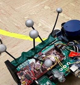
我们的机器人有一条路径,我们可以运行轮子,但我们如何让机器人顺利地跟随轨道?首先,我们确保我们始终知道我们的机器人汽车在哪里。OptiTrack Motive 软件允许我用我打印的 3D 打印将一些反光球绑在我的机器人车的顶部,它会跟踪这些球的中心。然后我可以将它用作我的机器人汽车的中心,这样我就可以始终准确地知道它在网格中的位置。
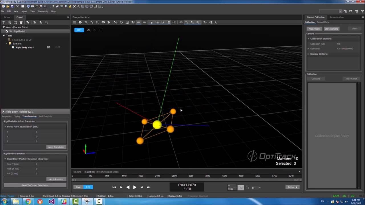
我们使用下面的代码读取将通过 SPIRXC 使用的数据。
障碍物检测
现在,困难的部分来了。机器人如何知道有什么东西挡住了它,我们如何围绕它进行计划?我所做的是给机器人一些规则。“障碍只能在这些地方,如果你看到那个区域周围的东西就是那个地方的障碍”。听起来很容易,对吧?我继续为可能成为障碍的 48 条边制定规则。
obs[46].x = 5; //ROBOTps
    obs[46].y = 6;
    obs[46].tally = 0;
    obs[46].found = 0;
    obs[46].idx1 = 72;
    obs[46].idx2 = 71;
    obs[46].idx3 = 70;
    obs[47].x = 3; //ROBOTps
    obs[47].y = 6;
    obs[47].tally = 0;
    obs[47].found = 0;
    obs[47].idx1 = 70;
    obs[47].idx2 = 69;
    obs[47].idx3 = 68;
    obs[48].x = 1; //ROBOTps
    obs[48].y = 6;
    obs[48].tally = 0;
    obs[48].found = 0;
    obs[48].idx1 = 68;
    obs[48].idx2 = 67;
    obs[48].idx3 = 66;
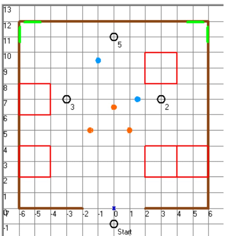
然后,我确保找到每个障碍物的中心及其对应的路线图索引。如果发现障碍物,我会计算出来。如果它达到 4 个或更多计数,我将地图中的那些“0”更改为“X”,然后再次运行 A* 并获得一条新路径。
为此,我首先必须知道我的激光雷达读数在全球范围内的距离。由于 LIDAR 和 OptiTrack 系统有不同的基础,我必须确保它们是相同的,代码如下。
if (UseLIDARping == 1) {
            UseLIDARping = 0;
            int i = 0;
            // change of basis
            for (i = 0; i < 360; i++) {
                //if the data is not available, set all of them to 0 to avoid messing things up
                if (pingpts[i].distance ==0) {
                    x_f[i].distance = 0;
                    y_f[i].distance = 0;
                    x_f[i].timestamp = pingpts[i].timestamp;
                    y_f[i].timestamp = pingpts[i].timestamp;
                } else {
                    x_ori[i] = pingpts[i].distance*cos(i*0.01745329)/304;//0.017453292519943 is pi/180
                    y_ori[i] = pingpts[i].distance*sin(i*0.01745329)/304;
                    x_f[i].distance = (x_ori[i])*sin(ROBOTps.theta)+(y_ori[i])*cos(ROBOTps.theta)+(ROBOTps.x); //change basis
                    y_f[i].distance = (x_ori[i])*cos(ROBOTps.theta)+(y_ori[i])*sin(ROBOTps.theta)+(ROBOTps.y); //change basis
//                    x_f[i].distance = (x_ori[i]+pose_x)*cos(pose_rad)-(y_ori[i]+pose_y)*sin(pose_rad); //change basis
//                    y_f[i].distance = (x_ori[i]+pose_x)*sin(pose_rad)+(y_ori[i]+pose_y)*cos(pose_rad); //change basis
                }
            }
            if (PathFunction == 2){
                searchObs();
            }
这也是搜索并查看我是否有障碍的好时机。为了搜索障碍物,我必须对每个障碍物进行 FOR 循环,看看 LIDAR 读数与其对应的 x 和 y 位置之间的差异是否小于 0.35 英尺。
void searchObs(){
    int i = 0;
    for(i = 0; i < 49; i++){
        // search lidar angles
//        }
        if(x_ori[90] < 1.5 && x_ori[90] > 0){
            if(y_ori[90] < 1.5 && y_ori[90] > 0){
                obsDisx = (x_f[90].distance - obs[i].x);
                obsDisy = (y_f[90].distance - obs[i].y);
                obsDist = sqrtf((obsDisx*obsDisx)*(obsDisy*obsDisy));
                if(obsDist < 0.35){
                    obs[i].tally++;
                }
            }
        }
我又做了 4 个角度,45、135、170 和 10 度。如果计数达到 4,则它们正式成为障碍并标记为已找到。然后,该函数给出一个标志 obsSearch,表示发现了一个障碍物,告诉机器人停止并寻找新路径。
if(obs[i].tally > 3){
            if (obs[i].found == 0){
                mapCourseStart[obs[i].idx1] = 'x';
                mapCourseStart[obs[i].idx2] = 'x';
                mapCourseStart[obs[i].idx3] = 'x';
                //Flag that an obs has been found
                obsSearch = 1;
                obs[i].found = 1;
            }
        }
把它们放在一起
把它们放在一起!首先,我制作了一个“PathFunction”标志,它会告诉机器人它处于什么状态。它可以是“1”,即 A*,“2”,即跟随路径并寻找障碍物,或“3”,即 STANDBYE . 机器人由一个按钮启动。
void ReadSwitches(void) {
    if(GpioDataRegs.GPADAT.bit.GPIO4 == 0){
        PathFunction = 1;
    }
    if(GpioDataRegs.GPADAT.bit.GPIO5 == 0){
        PathFunction = 2;
    }
    if(GpioDataRegs.GPADAT.bit.GPIO6 == 0){
        PathFunction = 0;
    }
    if(GpioDataRegs.GPADAT.bit.GPIO7 == 0){
        PathFunction = 3;
    }
}
要开始按下按钮运行 A*,这将在空白地图上提供到端点的路径,并将“PathFunction”推到 2。
if(PathFunction == 2){ // DRIVE THE PATH AFTER A*  !!USE Lidar and obstacle indentification to interrupt PATHFUCTION = 2
        //Run xycontrol for first path node changing desired x and y after each iteration until PathLen amount of times.
        //This should end at the end of the path !!MUST WATCH FOR SLIPPING OF WHEELS!!
        if(target_near == 1){
            nodenumber++; //progress in path
            target_near = 0;
        }
        //A*
        if(obsSearch == 1){
            if(astarC < 50){
                PathFunction = 1;
                nodenumber = 0;
            }
//            PathFunction = 1;
//            nodenumber = 0;
        }
一旦“PathFunction = 2”,我们首先检查我们是否靠近目标。如果我们是,我们说要在道路上进步。如果没有,我们在继续前进之前检查是否发现了障碍物。如果我们找到一个,obsSearch = 1,我们回到 A*。如果没有,我们可以自由地转到所需的节点。
x_desired = (path[nodenumber+1].col);
        y_desired = (path[nodenumber+1].row);
        x_pos = ROBOTps.x;
        y_pos = ROBOTps.y;
        thetaabs = ROBOTps.theta;
        xy_control(&vref_forxy, &turn_forxy,turn_thres,x_pos,y_pos,x_desired,y_desired,
                   thetaabs,target_radius,target_radius_near);
        Vref = vref_forxy;
        turn = turn_forxy;
        if(nodenumber == pathLen-1){  //end of path!
            PathFunction = 3;
            Vref = 0;
            turn = 0;
        }
我们计算所需的 x 和 y 并使用动作捕捉更新机器人的位置。然后我们运行 xy_control 来更新 Vref 和 Turn。最后,我们检查我们是否到达了路径的尽头。如果是这样,我们将等待进一步指示。
项目成果!
在我了解结果之前,我想说我在这个项目上玩得很开心,我在这个项目中学到了比以前更多的机器人技术。如果您觉得这很有趣,请尝试一下。
A* 路径规划结果!
A* 的结果非常棒,因为机器人在轨道上缩放,精确地避开了我在地图上手动放置的每一个障碍物。
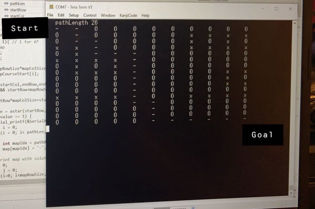
以上是项目的A*路径规划、xy_control、动作捕捉组合的结果。机器人很容易跟随给它的路径,轻松地躲避障碍物。
障碍物检测结果!
到目前为止,障碍物检测是该项目中最难的部分。机器人汽车在静止时能够可靠地看到和映射障碍物,但在转弯和移动时会遇到一些麻烦。
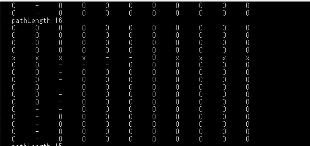
以上是自主机器人汽车的成功运行之一。
在这里,您可以看到机器人清楚地发现了两个障碍物并改变了路线以绕过它们。
上面你可以看到机器人尝试 A* 离开然后找到一个幻影障碍物并撞到另一个障碍物。
总的来说,这个项目是一个巨大的成功!这显然可以调整和改进,但该项目的理论和代码使一个现实生活中的自主机器人。
谢谢你
如果没有 Dan Block 教授的帮助,我不可能做到这一点,因为他不仅提供了材料,而且还以他力所能及的方式提供了帮助!谢谢,丹!
我希望你喜欢我的项目,并在此过程中学到了一些东西。感谢您的时间!
声明:本文内容及配图由入驻作者撰写或者入驻合作网站授权转载。文章观点仅代表作者本人,不代表电子发烧友网立场。文章及其配图仅供工程师学习之用,如有内容侵权或者其他违规问题,请联系本站处理。 举报投诉
- 相关下载
- 相关文章


