
资料下载

带有OV7670相机模块的TinyML
描述
这是我在 TensorFlow 下与 Google Summer of Code (GSoC) 合作的第二个项目。互联网上没有合适的文档来构建自定义图像识别 TinyML 模型,因此我的 GSoC 导师 Paul Ruiz 建议我尝试解决它。您还可以通过以下方式构建图像识别 TinyML 应用程序。快乐修补!
项目背后的想法:
我想解决一个变量较少的问题,因为有关如何使用相机模块和处理其数据的文档不是很好。我选择构建一个 MNIST TinyML 模型,因为在这种情况下,我不需要担心训练数据集,它可以让我专注于项目的重要部分,以启动和运行项目。但是,既然我已经了解了构建自定义图像识别项目的所有部分,我已经记录了如何使用相机模块收集训练数据集。
博客的主题/基调?
我想警告您,这个博客可能有点难以理解。对此有一个正确的解释:使用基于加速度计的应用程序,只需在串行监视器或绘图仪上打印出一个轴的加速度计值,就可以很容易地进行健全性检查。相比之下,对图像识别应用程序进行健全性检查至少要烦人 10 倍,因为检查一段代码是否正在执行所需的操作无法实时可视化。
一些评论
由于单元测试的复杂性,这篇博客可能有点难以理解。我想通过读者的反馈来解决解释中的任何差距。因此,请在下方评论您对嵌入式系统图像识别相关的任何疑问和问题。
TinyML 有意义吗?
我建议您通读 TinyML 书的作者 Pete Warden 的这篇精彩文章,以了解为什么在微控制器上运行机器学习模型是有意义的,并且是机器学习的未来。
即使 TinyML 有意义,图像识别在 TinyML 上有意义吗?
我们将在此处使用的 OV7670 相机输出的完整 VGA(640×480 分辨率)对于当前的 TinyML 应用程序来说太大了。uTensor 通过使用 28×28 图像的 MNIST 运行手写检测。TensorFlow Lite for Microcontrollers 示例中的人员检测示例使用 96×96,这已经足够了。即使是最先进的“Big ML”应用程序也通常只使用 320×320 的图像。总之,在微型微控制器上运行图像识别应用程序非常有意义

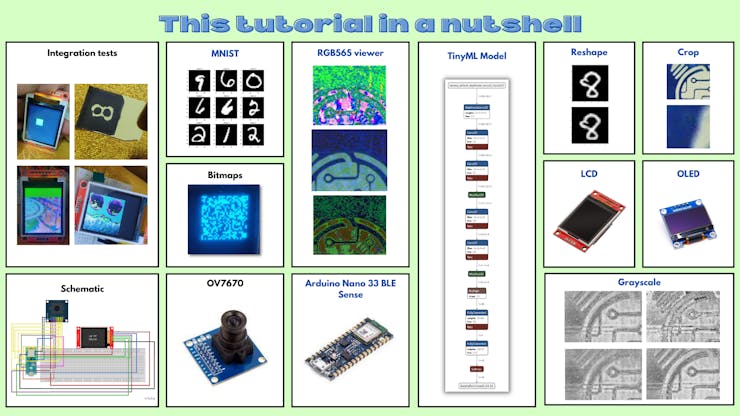
本教程简而言之:
- 接线
- OV7670摄像头模组介绍
- RGB888 与 RGB565
- 结论
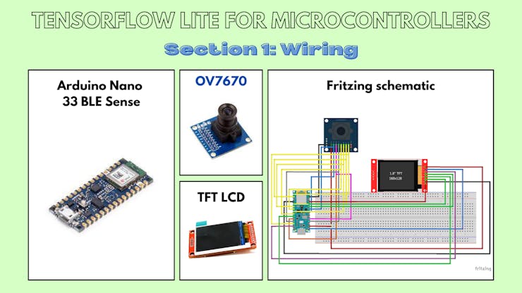
1、接线
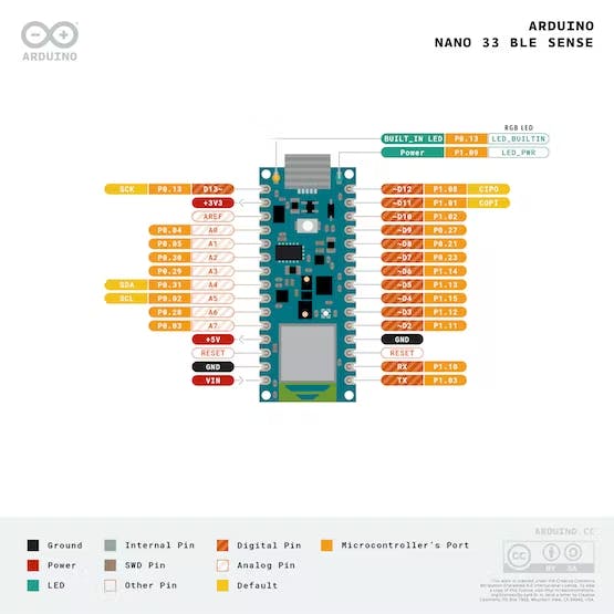
1.a Arduino Nano 33 BLE Sense 引出线
1.b 原理图
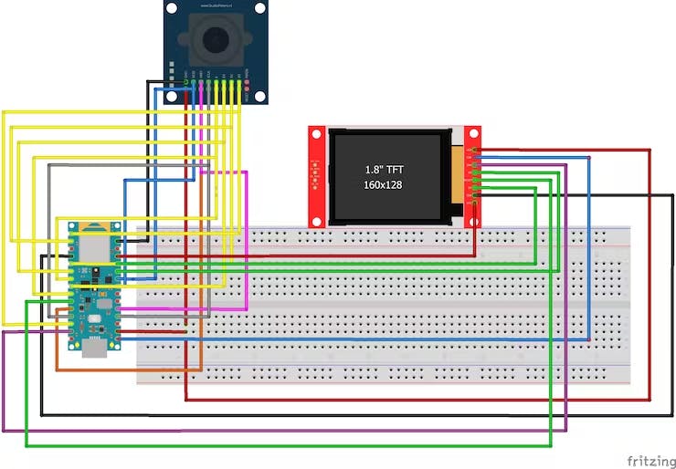
1.c Arduino Nano 33 BLE Sense - OV7670 摄像头模块
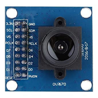
OV7670 相机模块上的引脚 - Arduino Nano 33 BLE Sense 上的引脚
3.3 至 3.3V
接地到接地
SIOC 至 A5
SIOD 至 A4
VSYNC 至 8
HREF 到 A1
PCLK 到 A0
XCLK 至 9
D7 至 4
D6至6
D5至5
D4 至 3
D3 至 2
D2 至 0 / RX
D1 到 1 / TX
D0 至 10
1.d Arduino Nano 33 BLE Sense - TFT LCD 模块
1.44" TFT LCD 显示屏上的引脚 - Arduino Nano 33 BLE Sense 上的引脚
注意:Arduino 板上只有一个 3.3V。使用面包板与其建立多个连接。
LED 至 3.3V
SCK 至 13
SDA 至 11
A0 至 A6
重置为 7
CS到A7
接地到接地
VCC 至 5V
注意:连接到 Arduino 板的 TFT LCD 模块使用硬件 SPI 引脚。
SPI代表串行外设接口。微控制器使用它与一个或多个外围设备快速通信。SPI 通信比 I2C 通信更快。
所有外围设备共有三个公共引脚:
SCK - 它代表串行时钟。该引脚产生时钟脉冲,用于同步数据传输。
MISO - 它代表主输入/从输出。MISO 引脚中的这条数据线用于向主机发送数据。
MOSI - 它代表主输出/从输入。该线用于向从站/外围设备发送数据。
开发板上的 SPI 引脚:
- D13-SCK
- D12 - 味噌
- D11 - 莫西
我们将只在此处使用 SCK 和 MOSI 引脚,因为我们将向 TFT 发送数据并且不需要 MISO 引脚。
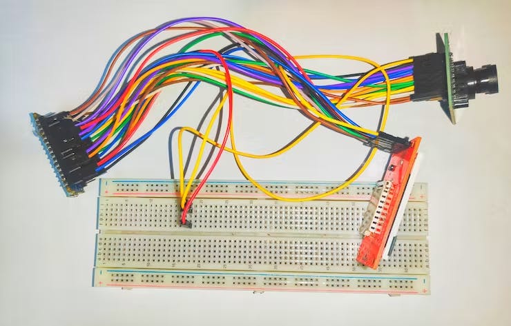
二、OV7670摄像头模组介绍
2.a OV7670模块的一般信息
OV7670 摄像头模块是一款低成本的 0.3 兆像素 CMOS 彩色摄像头模块。它可以 30fps 的速度输出 640x480 VGA 分辨率的图像。
特征:
- 低光操作的高灵敏度
- 嵌入式便携式应用的低工作电压
- 镜头阴影校正
- 闪烁 (50/60 Hz) 自动检测
- 降噪电平自动调整
- 支持图像尺寸:VGA、CIF 以及从 CIF 缩小到 40x30 的任何尺寸
- 用于子采样的 VarioPixel 方法
- 自动图像控制功能包括:自动曝光控制(AEC)、自动增益控制(AGC)、自动白平衡(AWB)、自动带状滤波器(ABF)、自动黑电平校准(ABLC)
- ISP 包括降噪和缺陷校正
- 支持LED和闪光灯频闪模式
- 支持缩放
- 输出支持 Raw RGB、RGB(GRB 4:2:2、RGB565/555/444)、YUV (4:2:2) 和 YCbCr (4:2:2) 格式
- 图像质量控制包括色彩饱和度、色调、伽马、锐度(边缘增强)和防晕染
- 饱和度自动调整(UV调整)
- 边缘增强级别自动调整
规格:
- 感光阵列:640 x 480。
- IO 电压:2.5V 至 3.0V。
- 工作功率:60mW/15fpsVGAYUV。
- 休眠模式:<20μA。
- 工作温度:-30 至 70 摄氏度。
- 输出格式:YUV/YCbCr4:2:2 RGB565/555/444 GRB4:2:2 原始 RGB 数据(8 位)。
- 镜头尺寸:1/6 英寸。
- 视角:25度。
- 最大限度。帧速率:30fps VGA。
- 灵敏度:1.3V / (Lux-sec)。
- 信噪比:46 分贝。
- 动态范围:52 分贝。
- 浏览方式:按行。
- 电子曝光:1 至 510 行。
- 像素覆盖范围:3.6μm x 3.6μm。
- 鸭电流:60℃时为 12 mV/s。
- PCB 尺寸(长 x 宽):约 1.4 x 1.4 英寸/3.5 x 3.5 厘米。
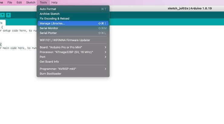
2.b 软件设置:安装“Arduino_OV767x”库
首先,您需要安装 Arduino IDE。接下来,在“工具”部分下,单击“管理库”,搜索OV7670 ,选择Arduino_OV767x库并单击“安装”。
OV767X 库中支持的图像配置:
- VGA – 640 x 480
- CIF – 352 x 240
- QVGA – 320 x 240
- QCIF – 176 x 144

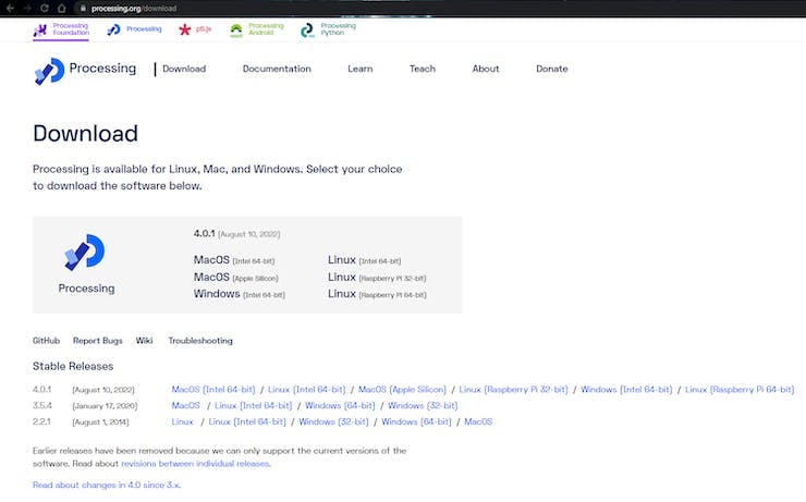
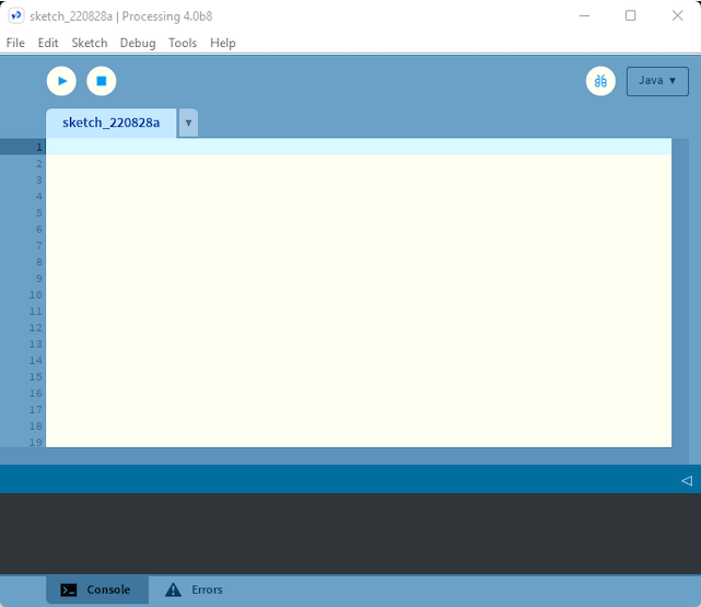
2.c 软件设置:安装Processing
Processing是一个简单的编程环境,由麻省理工学院媒体实验室的研究生创建,旨在更轻松地开发以动画为重点的面向视觉的应用程序,并通过交互为用户提供即时反馈。
使用此链接下载并安装 Processing 。
为什么我需要下载这个软件?我们将使用此应用程序可视化 OV7670 相机模块通过串行端口发送的相机输出。
2.d 使用处理:测试模式
本小节的 Github 链接。
打开一个 Arduino 草图,将下面的草图复制并粘贴到草图中,将其上传到您的电路板。
Processing_test_pattern.ino:
/*
  Circuit:
    - Arduino Nano 33 BLE board
    - OV7670 camera module:
      - 3.3 connected to 3.3
      - GND connected GND
      - SIOC connected to A5
      - SIOD connected to A4
      - VSYNC connected to 8
      - HREF connected to A1
      - PCLK connected to A0
      - XCLK connected to 9
      - D7 connected to 4
      - D6 connected to 6
      - D5 connected to 5
      - D4 connected to 3
      - D3 connected to 2
      - D2 connected to 0 / RX
      - D1 connected to 1 / TX
      - D0 connected to 10
*/

#include

int bytesPerFrame;

byte data[320 * 240 * 2]; // QVGA: 320x240 X 2 bytes per pixel (RGB565)

void setup() {
  Serial.begin(115200);
  while (!Serial);

  if (!Camera.begin(QVGA, RGB565, 1)) {
    Serial.println("Failed to initialize camera!");
    while (1);
  }

  bytesPerFrame = Camera.width() * Camera.height() * Camera.bytesPerPixel();

  Camera.testPattern();
}

void loop() {
  Camera.readFrame(data);

  Serial.write(data, bytesPerFrame);
}
将上述草图上传到 Arduino 板后,打开 Processing 应用程序并将以下代码复制粘贴到一个新文件中。
处理草图:
import processing.serial.*;
import java.nio.ByteBuffer;
import java.nio.ByteOrder;

Serial myPort;

// must match resolution used in the sketch
final int cameraWidth = 320;
final int cameraHeight = 240;

final int cameraBytesPerPixel = 2;

final int bytesPerFrame = cameraWidth * cameraHeight * cameraBytesPerPixel;

PImage myImage;

void setup()
{
  size(320, 240);

  // if you have only ONE serial port active
  //myPort = new Serial(this, Serial.list()[0], 9600); // if you have only ONE serial port active

  // if you know the serial port name
  //myPort = new Serial(this, "COM5", 9600);                    // Windows
  //myPort = new Serial(this, "/dev/ttyACM0", 9600);             // Linux
  myPort = new Serial(this, "/dev/cu.usbmodem14101", 9600);  // Mac

  // wait for full frame of bytes
  myPort.buffer(bytesPerFrame);

  myImage = createImage(cameraWidth, cameraHeight, RGB);
}

void draw()
{
  image(myImage, 0, 0);
}

void serialEvent(Serial myPort) {
  byte[] frameBuffer = new byte[bytesPerFrame];

  // read the saw bytes in
  myPort.readBytes(frameBuffer);

  // create image to set byte values
  PImage img = createImage(cameraWidth, cameraHeight, RGB);

  // access raw bytes via byte buffer
  ByteBuffer bb = ByteBuffer.wrap(frameBuffer);
  bb.order(ByteOrder.BIG_ENDIAN);

  int i = 0;

  img.loadPixels();
  while (bb.hasRemaining()) {
    // read 16-bit pixel
    short p = bb.getShort();

    // convert RGB565 to RGB 24-bit
    int r = ((p >> 11) & 0x1f) << 3;
    int g = ((p >> 5) & 0x3f) << 2;
    int b = ((p >> 0) & 0x1f) << 3;

    // set pixel color
    img.pixels[i++] = color(r, g, b);
  }
  img.updatePixels();

  // assign image for next draw
  myImage = img;
}
现在,在上面取消注释特定于您的操作系统的行。然后单击“运行”按钮。
// if you know the serial port name
  //myPort = new Serial(this, "COM5", 9600);                    // Windows
  //myPort = new Serial(this, "/dev/ttyACM0", 9600);             // Linux
  //myPort = new Serial(this, "/dev/cu.usbmodem14101", 9600);  // Mac
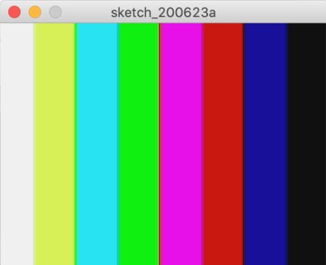
您应该得到如下所示的输出:
2.e 解释:测试模式
Processing_test_pattern.ino:
byte data[320 * 240 * 2]; // QVGA: 320x240 X 2 bytes per pixel (RGB565)
这行代码建立了一个 byte 类型的数组。我们将使用 RGB565 颜色格式,因此每个像素需要 2 个字节,我们将在此处使用的图像格式是 QVGA,大小为 320x240 像素。因此,数组的大小将是每个像素的颜色所需的高度 * 宽度 * 字节数。实际上,它转换为320 * 240 * 2 。
Serial.begin(115200);
  while (!Serial);
这行代码设置了串口,用于在计算机和单片机之间传输数据。
if (!Camera.begin(QVGA, RGB565, 1)) {
    Serial.println("Failed to initialize camera!");
    while (1);
  }
上面的代码行设置了 OV7670 摄像头模块。在本例中,我们已将其初始化为使用QVGA图像格式和RGB565颜色格式。
Camera.testPattern();
这行代码设置相机通过串行端口发送测试图像。
Camera.readFrame(data);
这行代码从摄像头中读取一帧图像并将其存储在我们之前声明的数组中。
Serial.write(data, bytesPerFrame);
最后,这行代码将数组的值写入串行监视器。
处理草图:
// must match resolution used in the sketch
final int cameraWidth = 320;
final int cameraHeight = 240;
这些代码行设置 cameraWidth 和 cameraHeight 以匹配 Arduino 草图中的大小。
// if you know the serial port name
  //myPort = new Serial(this, "COM5", 9600);                    // Windows
  //myPort = new Serial(this, "/dev/ttyACM0", 9600);             // Linux
  //myPort = new Serial(this, "/dev/cu.usbmodem14101", 9600);  // Mac
这些代码行指定了微控制器和计算机之间传输数据的串行端口。
// convert RGB565 to RGB 24-bit
    int r = ((p >> 11) & 0x1f) << 3;
    int g = ((p >> 5) & 0x3f) << 2;
    int b = ((p >> 0) & 0x1f) << 3;
这些代码行将 RGB565 颜色格式转换为 RGB888 格式以显示在您的计算机屏幕上。这将在后面的章节中详细解释。
2.f 使用处理:实时图像
本小节的 Github 链接。
打开一个 Arduino 草图,将下面的草图复制并粘贴到草图中,将其上传到您的电路板。
Processing_ov7670_live_image.ino
/*
  Circuit:
    - Arduino Nano 33 BLE board
    - OV7670 camera module:
      - 3.3 connected to 3.3
      - GND connected GND
      - SIOC connected to A5
      - SIOD connected to A4
      - VSYNC connected to 8
      - HREF connected to A1
      - PCLK connected to A0
      - XCLK connected to 9
      - D7 connected to 4
      - D6 connected to 6
      - D5 connected to 5
      - D4 connected to 3
      - D3 connected to 2
      - D2 connected to 0 / RX
      - D1 connected to 1 / TX
      - D0 connected to 10
*/

#include

int bytesPerFrame;

byte data[320 * 240 * 2]; // QVGA: 320x240 X 2 bytes per pixel (RGB565)

void setup() {
  Serial.begin(115200);
  while (!Serial);

  if (!Camera.begin(QVGA, RGB565, 1)) {
    Serial.println("Failed to initialize camera!");
    while (1);
  }

  bytesPerFrame = Camera.width() * Camera.height() * Camera.bytesPerPixel();

  Camera.testPattern();
}

void loop() {
  Camera.readFrame(data);

  Serial.write(data, bytesPerFrame);
}
将上述草图上传到 Arduino 板后,打开 Processing 应用程序并将以下代码复制粘贴到一个新文件中。
处理草图:
import processing.serial.*;
import java.nio.ByteBuffer;
import java.nio.ByteOrder;

Serial myPort;

// must match resolution used in the sketch
final int cameraWidth = 320;
final int cameraHeight = 240;

final int cameraBytesPerPixel = 2;

final int bytesPerFrame = cameraWidth * cameraHeight * cameraBytesPerPixel;

PImage myImage;

void setup()
{
  size(320, 240);

  // if you have only ONE serial port active
  //myPort = new Serial(this, Serial.list()[0], 9600); // if you have only ONE serial port active

  // if you know the serial port name
  //myPort = new Serial(this, "COM5", 9600);                    // Windows
  //myPort = new Serial(this, "/dev/ttyACM0", 9600);             // Linux
  myPort = new Serial(this, "/dev/cu.usbmodem14101", 9600);  // Mac

  // wait for full frame of bytes
  myPort.buffer(bytesPerFrame);

  myImage = createImage(cameraWidth, cameraHeight, RGB);
}

void draw()
{
  image(myImage, 0, 0);
}

void serialEvent(Serial myPort) {
  byte[] frameBuffer = new byte[bytesPerFrame];

  // read the saw bytes in
  myPort.readBytes(frameBuffer);

  // create image to set byte values
  PImage img = createImage(cameraWidth, cameraHeight, RGB);

  // access raw bytes via byte buffer
  ByteBuffer bb = ByteBuffer.wrap(frameBuffer);
  bb.order(ByteOrder.BIG_ENDIAN);

  int i = 0;

  img.loadPixels();
  while (bb.hasRemaining()) {
    // read 16-bit pixel
    short p = bb.getShort();

    // convert RGB565 to RGB 24-bit
    int r = ((p >> 11) & 0x1f) << 3;
    int g = ((p >> 5) & 0x3f) << 2;
    int b = ((p >> 0) & 0x1f) << 3;

    // set pixel color
    img.pixels[i++] = color(r, g, b);
  }
  img.updatePixels();

  // assign image for next draw
  myImage = img;
}
现在,在上面取消注释特定于您的操作系统的行。然后单击“运行”按钮。
// if you know the serial port name
  //myPort = new Serial(this, "COM5", 9600);                    // Windows
  //myPort = new Serial(this, "/dev/ttyACM0", 9600);             // Linux
  //myPort = new Serial(this, "/dev/cu.usbmodem14101", 9600);  // Mac
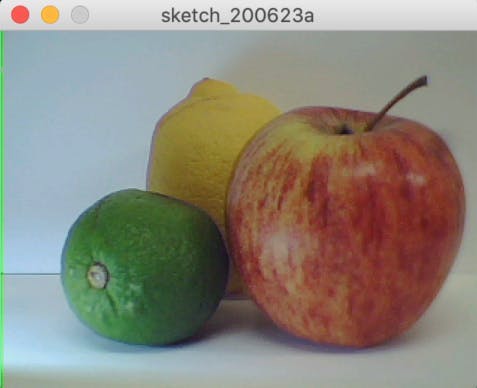
您应该得到如下所示的输出:
2.g 解释:实时图像
Processing_ov7670_live_image.ino:
byte data[320 * 240 * 2]; // QVGA: 320x240 X 2 bytes per pixel (RGB565)
这行代码建立了一个 byte 类型的数组。我们将使用 RGB565 颜色格式,因此每个像素需要 2 个字节,我们将在此处使用的图像格式是 QVGA,其大小为 320x240 像素。因此,数组的大小将是每个像素颜色所需的高度 * 宽度 * 字节数。实际上,它转换为320 * 240 * 2 。
Serial.begin(115200);
  while (!Serial);
这行代码设置了串口,用于在计算机和单片机之间传输数据。
if (!Camera.begin(QVGA, RGB565, 1)) {
    Serial.println("Failed to initialize camera!");
    while (1);
  }
上面的代码行设置了 OV7670 摄像头模块。在本例中,我们已将其初始化为使用QVGA图像格式和RGB565颜色格式。
Camera.testPattern();
这行代码设置相机通过串行端口发送测试图像。
Camera.readFrame(data);
这行代码从摄像头中读取一帧图像并将其存储在我们之前声明的数组中。
Serial.write(data, bytesPerFrame);
最后,这行代码将数组写入串行监视器。
处理草图:
// must match resolution used in the sketch
final int cameraWidth = 320;
final int cameraHeight = 240;
这些代码行设置 cameraWidth 和 cameraHeight 以匹配 Arduino 草图中的大小。
// if you know the serial port name
  //myPort = new Serial(this, "COM5", 9600);                    // Windows
  //myPort = new Serial(this, "/dev/ttyACM0", 9600);             // Linux
  //myPort = new Serial(this, "/dev/cu.usbmodem14101", 9600);  // Mac
这些代码行指定了微控制器和计算机之间传输数据的串行端口。
// convert RGB565 to RGB 24-bit
    int r = ((p >> 11) & 0x1f) << 3;
    int g = ((p >> 5) & 0x3f) << 2;
    int b = ((p >> 0) & 0x1f) << 3;
这些代码行将 RGB565 颜色格式转换为 RGB888 格式,以便在您的计算机屏幕上显示。这将在后面的章节中详细解释。
2.h 这种方法的问题,以及可能的解决方案
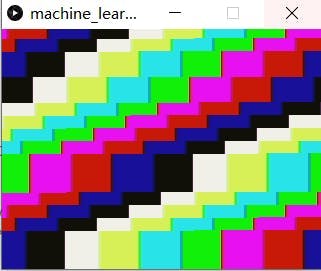
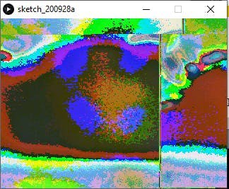
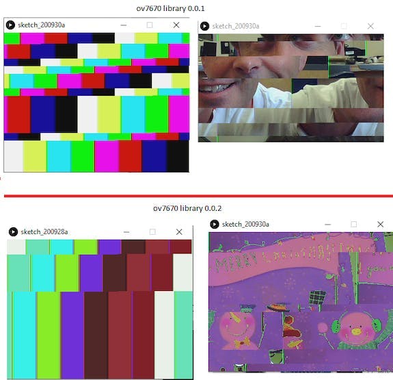
处理应用程序显示锯齿形测试图案而不是实际测试图案,并显示破损/褪色图像而不是正确的实时图像。这已在 Github 讨论和 Arduino 论坛中进行了讨论。我已将链接附加到下面的链接。
链接到 Github 讨论
链接到 Arduino 论坛
一些建议的解决方案:
1.使用较短的电线
- 我的看法:我将 20 厘米的电线更改为 10 厘米,但这并没有什么不同。
2. 试试 Ubuntu Linux
3.改变FPS
- 我的看法:我将其更改为 1/5/30 FPS,但没有任何改进。
4.更改串口速率
- 我的看法:我将串行速率从 9600 bps 更改为 115200 bps。但问题仍然没有改善
问题的合理原因:
- 论坛上的大多数人都认为导致问题的是 Windows 处理速度,切换到 Ubuntu 应该可以解决问题。
3. RGB888 与 RGB565
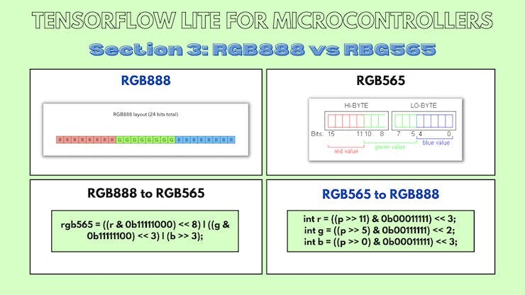
3.a 关于RGB888的一般信息
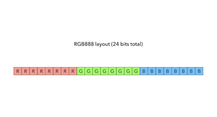
RGB888 颜色模型使用 8 位来表示每种颜色。透明度 (alpha) 值假定为最大值 (255)。
红色、蓝色和绿色可能的最大值为 255。
一些例子:
- 白色:(R, G, B) = (255, 255, 255)
- 黑色:(R, G, B) = (0, 0, 0)
3.b 关于RGB565的一般信息
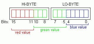
RGB565 用于以 16 位表示颜色,而不是 24 位来指定颜色。为了充分利用这 16 位,红色和蓝色编码为 5 位,绿色编码为 6 位。这是因为人眼能够更好地看到更多的绿色阴影。
RGB565 颜色格式中红色和蓝色值的最大可能值为 31,而绿色的最大值为 63。
有趣的事实:RGB565 只有 RGB888 颜色的 0.39%(65k 对 16m)
3.c 将 RGB888 值转换为 RGB565
/*
Assumption:
r = 8 bits
g = 8 bits
b = 8 bits
*/
rgb565 = ((r & 0b11111000) << 8) | ((g & 0b11111100) << 3) | (b >> 3);
我们转移:
- r左移 11 位,并丢弃最后 3 位
- g左移 5 位,并丢弃最后 2 位
- b右移 3 位以丢弃最后 3 位
我们最终按位或将这 3 个连接成一个 16 位表示。
例子:
让我们将白色从 RGB888 颜色空间转换为 RGB565 颜色空间。
由于我们已经知道两个颜色空间可能的最大可能值,我们应该期望
- RGB888颜色空间中的 (255, 255, 255)
- RGB565颜色空间中的 (31, 63, 31)
在这个问题中,
- r = 十进制的 255 或二进制的 0000000011111111
- g = 十进制的 255 或二进制的 0000000011111111
- b = 十进制的 255 或二进制的 0000000011111111
对于红色:
- r = 0000000011111111
- (r & 0b11111000) = 0000000011111000
- (r & 0b11111000) << 8) = 1111100000000000
对于绿色:
- g = 0000000011111111
- (g & 0b11111100) = 0000000011111100
- ((g & 0b11111100) << 3) = 0000011111100000
对于蓝色:
- b = 0000000011111111
- (b >> 3) = 0000000000011111
结合这三个等式:
- rgb565 = ((r & 0b11111000) << 8) | ((g & 0b11111100) << 3) | (b >> 3);
- rgb565 = ( 1111100000000000 | 0000011111100000 | 0000000000011111)
- rgb565 = 1111111111111111
在RGB565色彩空间中,
- 前5位对应红色值
- 接下来的 6 位对应绿色值
- 最后 5 位对应蓝色值
- 这转换为 (31, 63, 31),这是预期的输出!
3.d 将 RGB565 值转换为 RGB888
int r = ((p >> 11) & 0b00011111) << 3;
int g = ((p >> 5) & 0b00111111) << 2;
int b = ((p >> 0) & 0b00011111) << 3;
- 对于红色,我们左移 11 位,与 0b00011111 按位与,右移 3 位
- 对于绿色,我们左移 5 位,与 0b00111111 按位与,右移 2 位
- 对于蓝色,我们左移 0 位,与 0b00011111 按位与,右移 3 位
例子:
让我们将白色从 RGB565 颜色空间转换为 RGB888 颜色空间。
由于我们已经知道两个颜色空间可能的最大可能值,我们应该期望
- RGB565颜色空间中的 (31, 63, 31)
- RGB888颜色空间中的 (248, 252, 248)
我们不应该期望 RGB888 颜色空间中的 (255, 255, 255) 吗?
RGB565 只有 RGB888 颜色的 0.39%(65k 对 16m)。因此它无法覆盖 RGB888 的整个频谱。
在这个问题中,
在RGB 格式中,白色 = 1111111111111111
对于红色:
- p(此处:白色)= 1111111111111111
- (p >> 11) = 00011111
- ((p >> 11) & 0b00011111) = 00011111
- (((p >> 11) & 0b00011111) << 3) = 11111000
对于绿色:
- p(此处:白色)= 1111111111111111
- (p >> 5) = 0000011111111111
- ((p >> 5) & 0b00111111) = 00111111
- (((p >> 5) & 0b00111111) << 2) = 11111100
对于蓝色:
- p(此处:白色)= 1111111111111111
- (p >> 0) = 1111111111111111
- ((p >> 0) & 0b00011111) = 00011111
- ((p >> 0) & 0b00011111) << 3 = 11111000
结合这三个输出:
- 最终红色值 = 0b11111000 = 248
- 最终绿色值 = 0b11111100 = 252
- 最终蓝色值 = 0b11111000 = 248
- 这是预期的输出!
链接到 RGB565 颜色选择器
RGB88转RGB565转换器
结论
我感谢我的 GSoC 导师 Paul Ruiz,他在整个项目中指导我!
链接
声明:本文内容及配图由入驻作者撰写或者入驻合作网站授权转载。文章观点仅代表作者本人,不代表电子发烧友网立场。文章及其配图仅供工程师学习之用,如有内容侵权或者其他违规问题,请联系本站处理。 举报投诉
- 相关下载
- 相关文章


