
资料下载


如何制作手势控制机器人-MadeWithArduino(接收器PCB)
王雪
分享资料个
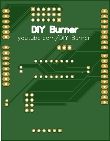
PCB图如下: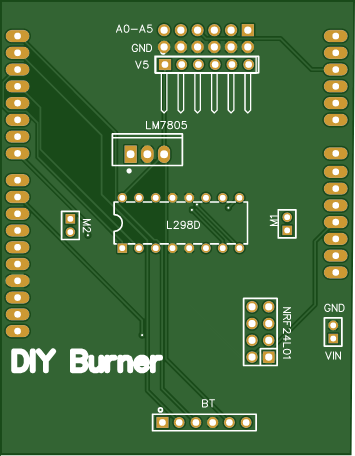
成分
| nRF24Lo1+ | × 1 |
| L298D电机驱动IC | × 1 |
| 7805稳压器 | × 1 |
| ARDUINO UNO REV3 | × 1 |
描述
如何制作手势控制机器人|| #MadeWithArduino(接收器 PCB)
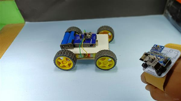
嘿,欢迎回到一个新项目。所以今天我们将学习使用Arduino创建一个手势控制车。
在这里我将分享项目的Receiver部分的详细教程,我还分享了另一个关于项目的Transmitter部分的教程。这是查看它的链接:https ://bit.ly/3z9FzZQ
查看 YouTube 上的项目教程视频:
首先说一下我们需要的材料:
〜阿杜诺乌诺
~ L298D 马达驱动IC
~ nRF24Lo1+
〜男性和女性头
~ 7805 5V 稳压器
~ 18650 电池
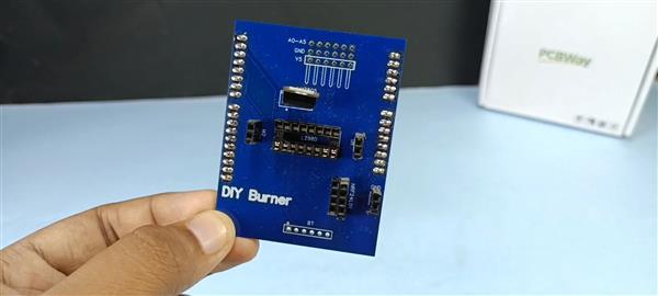
开始安装组件:
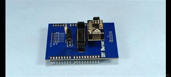
安排好上述组件后,我们需要将母头和公头引脚焊接到 PCB,如图所示。
现在,我们需要将组件一个一个地安装到 PCB 上。在以下模式中:
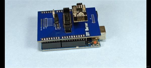
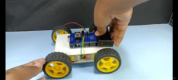
现在将 PCB 安装到 Arduino Uno 中。如下所示:
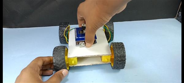
现在我们需要使用双面胶带将 Arduino Uno 安装到机箱中。
在此之后,我们需要将电机线连接到 PCB 电机输出引脚。
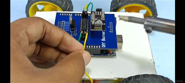
现在将电池座安装到机箱上,并将正极线连接到 PCB 的 Vin 引脚,将负极线连接到 PCB 的 GND 引脚。
安装完组件后,我们需要上传本文附件中给出的代码。
注意:在上传代码之前,请确保将 Arduino Uno 与您的计算机连接并包含所需的库。
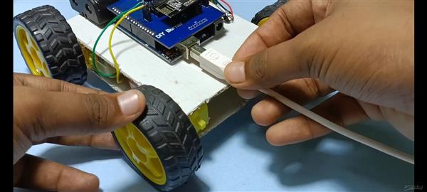
连接后,打开Arduino IDE并上传代码。
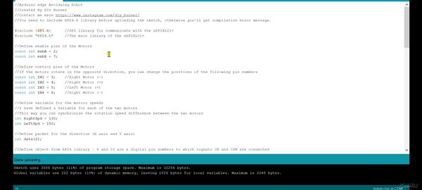
完成代码上传后,只需断开 Arduino Uno 与计算机的连接。
这就是这个项目的全部内容。请务必查看 Transmitter 项目教程 ( https://bit.ly/3z9FzZQ ) 并查看我们的 YouTube 教程视频:https ://youtu.be/h1LBA7dPYe0
谢谢你。
代码
手势控制汽车接收器代码
C/C++
| //Arduino Gesture control Receiver Code | |
| //Created By DIY Burner | |
| //Contact me here https://www.instagram.com/diy_burner/ | |
| //You need to include RF24.h library before uploading the sketch, otherwise you'll get compilation error message. | |
|
#include |
|
| #include "RF24.h" //The main library of the nRF24L01+ | |
| //Define enable pins of the Motors | |
| const int enbA = 2; | |
| const int enbB = 7; | |
| //Define control pins of the Motors | |
| //If the motors rotate in the opposite direction, you can change the positions of the following pin numbers | |
| const int IN1 = 3;//Right Motor (-) | |
| const int IN2 = 4;//Right Motor (+) | |
| const int IN3 = 5;//Left Motor (+) | |
| const int IN4 = 6;//Right Motor (-) | |
| //Define variable for the motors speeds | |
| //I have defined a variable for each of the two motors | |
| //This way you can synchronize the rotation speed difference between the two motors | |
| int RightSpd = 130; | |
| int LeftSpd = 150; | |
| //Define packet for the direction (X axis and Y axis) | |
| int data[2]; | |
| //Define object from RF24 library - 9 and 10 are a digital pin numbers to which signals CE and CSN are connected | |
| RF24 radio(8,9); | |
| //Create a pipe addresses for the communicate | |
| const uint64_t pipe = 0xE8E8F0F0E1LL; | |
| void setup(){ | |
| //Define the motor pins as OUTPUT | |
| pinMode(enbA, OUTPUT); | |
| pinMode(enbB, OUTPUT); | |
| pinMode(IN1, OUTPUT); | |
| pinMode(IN2, OUTPUT); | |
| pinMode(IN3, OUTPUT); | |
| pinMode(IN4, OUTPUT); | |
| Serial.begin(9600); | |
| radio.begin();//Start the nRF24 communicate | |
| radio.openReadingPipe(1, pipe); //Sets the address of the transmitter to which the program will receive data. | |
| radio.startListening(); | |
| } | |
| void loop(){ | |
| if (radio.available()){ | |
| radio.read(data, sizeof(data)); | |
| if(data[0] > 380){ | |
| //forward | |
| analogWrite(enbA, RightSpd); | |
| analogWrite(enbB, LeftSpd); | |
| digitalWrite(IN1, HIGH); | |
| digitalWrite(IN2, LOW); | |
| digitalWrite(IN3, HIGH); | |
| digitalWrite(IN4, LOW); | |
| } | |
| if(data[0] < 310){ | |
| //backward | |
| analogWrite(enbA, RightSpd); | |
| analogWrite(enbB, LeftSpd); | |
| digitalWrite(IN1, LOW); | |
| digitalWrite(IN2, HIGH); | |
| digitalWrite(IN3, LOW); | |
| digitalWrite(IN4, HIGH); | |
| } | |
| if(data[1] > 180){ | |
| //left | |
| analogWrite(enbA, RightSpd); | |
| analogWrite(enbB, LeftSpd); | |
| digitalWrite(IN1, HIGH); | |
| digitalWrite(IN2, LOW); | |
| digitalWrite(IN3, LOW); | |
| digitalWrite(IN4, HIGH); | |
| } | |
| if(data[1] < 110){ | |
| //right | |
| analogWrite(enbA, RightSpd); | |
| analogWrite(enbB, LeftSpd); | |
| digitalWrite(IN1, LOW); | |
| digitalWrite(IN2, HIGH); | |
| digitalWrite(IN3, HIGH); | |
| digitalWrite(IN4, LOW); | |
| } | |
| if(data[0] > 330 && data[0] < 360 && data[1] > 130 && data[1] < 160){ | |
| //stop car | |
| analogWrite(enbA, 0); | |
| analogWrite(enbB, 0); | |
| } | |
| } | |
| } |
声明:本文内容及配图由入驻作者撰写或者入驻合作网站授权转载。文章观点仅代表作者本人,不代表电子发烧友网立场。文章及其配图仅供工程师学习之用,如有内容侵权或者其他违规问题,请联系本站处理。 举报投诉
- 相关下载
- 相关文章


